Voltage controlled current source and frequency sweep device using same

A technology of voltage-controlled current source and frequency sweeper, applied in the field of frequency sweeper, can solve the problem that the current source cannot continuously control the current, and achieve the effect of accurate accuracy

Inactive Publication Date: 2008-01-30
BEYOND INNOVATION TECH
View PDF1 Cites 15 Cited by
  • Summary
  • Abstract
  • Description
  • Claims
  • Application Information

AI Technical Summary

Problems solved by technology

However, this kind of current source that uses switches S21~S2N to cont

Method used


Image

  • Voltage controlled current source and frequency sweep device using same
  • Voltage controlled current source and frequency sweep device using same
  • Voltage controlled current source and frequency sweep device using same

Examples


Embodiment Construction

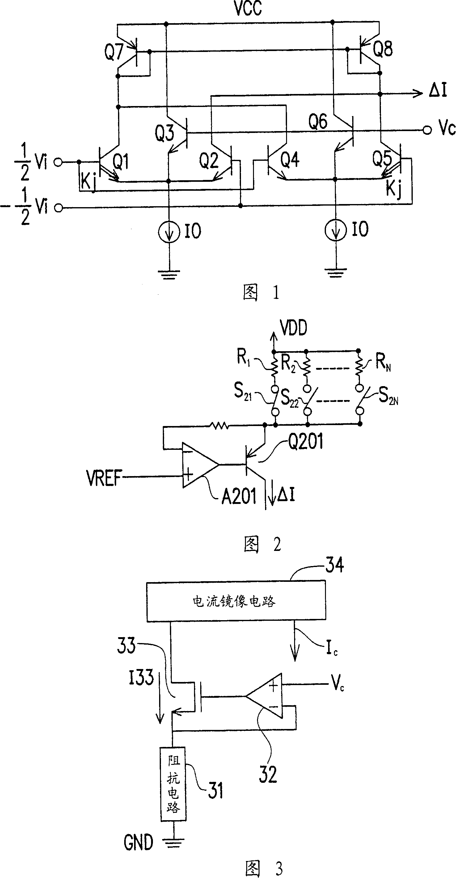
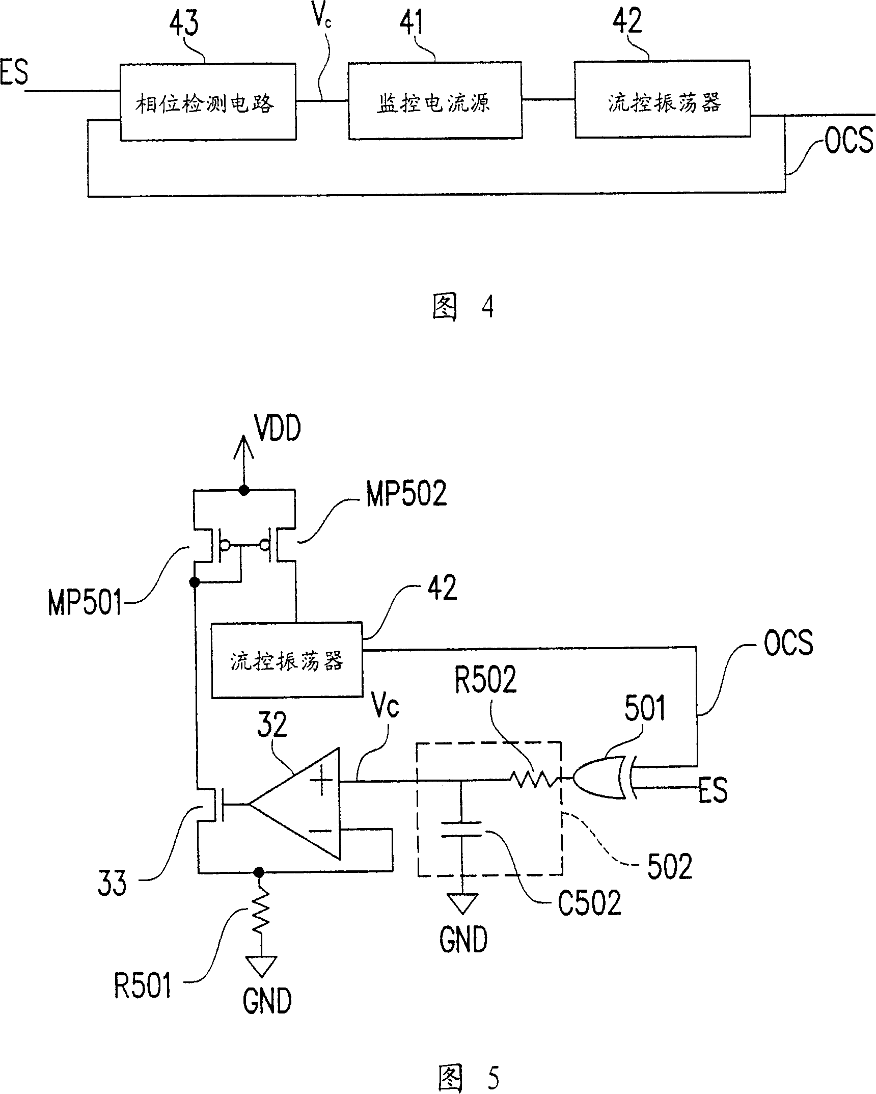
[0068] FIG. 3 shows a circuit diagram of a voltage-controlled current source according to an embodiment of the present invention. FIG. 4 shows a circuit diagram of a frequency sweeper using the voltage-controlled current source shown in FIG. 3 according to an embodiment of the present invention. Please refer to FIG. 4 first. The frequency sweeper circuit includes a voltage-controlled current source 41 , a current-controlled oscillator 42 and a phase detection circuit 43 as shown in FIG. 3 . The phase detection circuit 43 receives an external signal ES and an oscillating signal OCS output by the flow control oscillator 42 , and determines the magnitude of the output control voltage Vc according to the phase difference between the external signal ES and the oscillating signal OCS. The current-controlled oscillator 42 determines the frequency of the output oscillation signal OCS according to the magnitude of the controlled current Ic. The voltage-controlled current source 41 out...


PUM


Abstract

The invention relates to a voltage-controlled current source and a sweep device using the voltage-controlled current source, wherein, the voltage-controlled current source comprises an impedance circuit, an amplifier, a transistor and a current mirror circuit. The impedance circuit is coupled with a common voltage at one end, the amplifier is coupled with the other end of the impedance circuit at a first end and receives a controlled voltage at a second end, and the transistor is coupled with an output of the amplifier at the gate, and a first source/drain is coupled with the other end of the impedance circuit. The current mirror circuit is coupled with a second source/drain which comprises a current output, wherein, the current which is output from the current output is in proportion to the current passing the transistor.

Description

technical field [0001] The present invention relates to a voltage-controlled current source, and in particular to a voltage-controlled current source and a frequency sweeper using the voltage-controlled current source. Background technique [0002] Many electronic and communication devices always require the use of current sources. In the design of analog circuits, designing a good current source is a difficult point in circuit design, especially when the load changes greatly or some mechanism is required to control the output current of the current source. [0003] FIG. 1 shows a circuit diagram of a voltage-controlled current source in the form of an operational transconductance amplifier (OTA) proposed by the known US Pat. No. 5,815,039. Please refer to FIG. 1, the circuit includes BJT transistors Q1-Q8 and two current sources IO. The circuit is mainly based on the differential input voltage (marked 1 / 2ΔVi and -1 / 2ΔVi in Figure 1), that is, the difference between the ba...

Claims


Application Information

Patent Timeline
IPC IPC(8): G05F3/16H04N17/04
Inventor 余仲哲
Owner BEYOND INNOVATION TECH
Why Eureka
Try Eureka