
Semiconductor device and method of manufacturing the same

A manufacturing method and semiconductor technology, applied in the direction of semiconductor/solid-state device manufacturing, semiconductor devices, electric solid-state devices, etc., can solve the problems of not becoming a product chip, product reliability and qualified product rate deterioration, etc., to reduce adverse situations, reliable Good quality and high qualified product rate, and the effect of improving production efficiency

Inactive Publication Date: 2008-01-30
SANYO ELECTRIC CO LTD +2
View PDF1 Cites 14 Cited by
  • Summary
  • Abstract
  • Description
  • Claims
  • Application Information

AI Technical Summary

Problems solved by technology

As described above, since the portion covered by the holding member 112 cannot be properly etched, it cannot be used as a product chip in general.
Therefore, in the case of using the holding member to fix the semiconductor substrate on the stage, the position of the holding member is slightly shifted when the etching process and the ashing process are repeated, and there are also problems in the reliability and reliability of the final product. The problem of deterioration of the qualified product rate

Method used


Image

  • Semiconductor device and method of manufacturing the same
  • Semiconductor device and method of manufacturing the same
  • Semiconductor device and method of manufacturing the same

Examples


Embodiment Construction

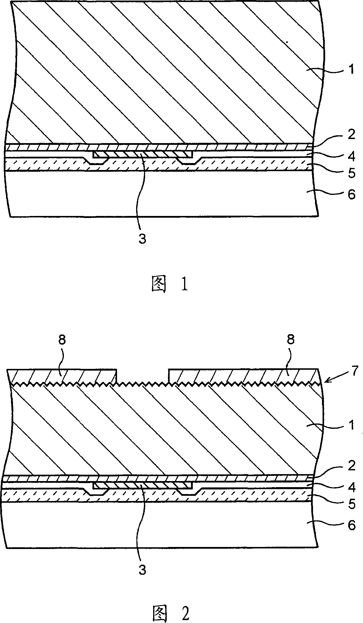
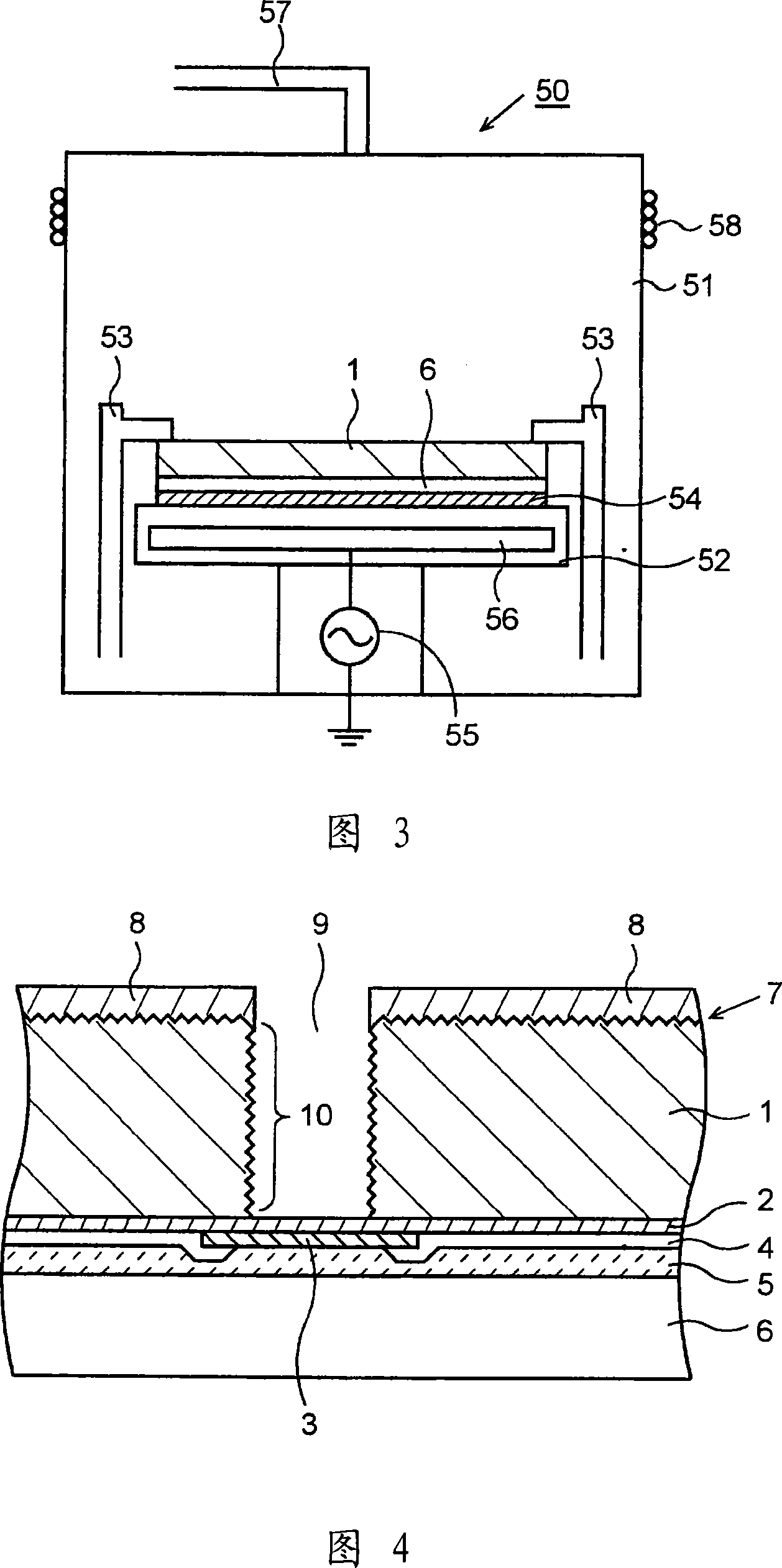
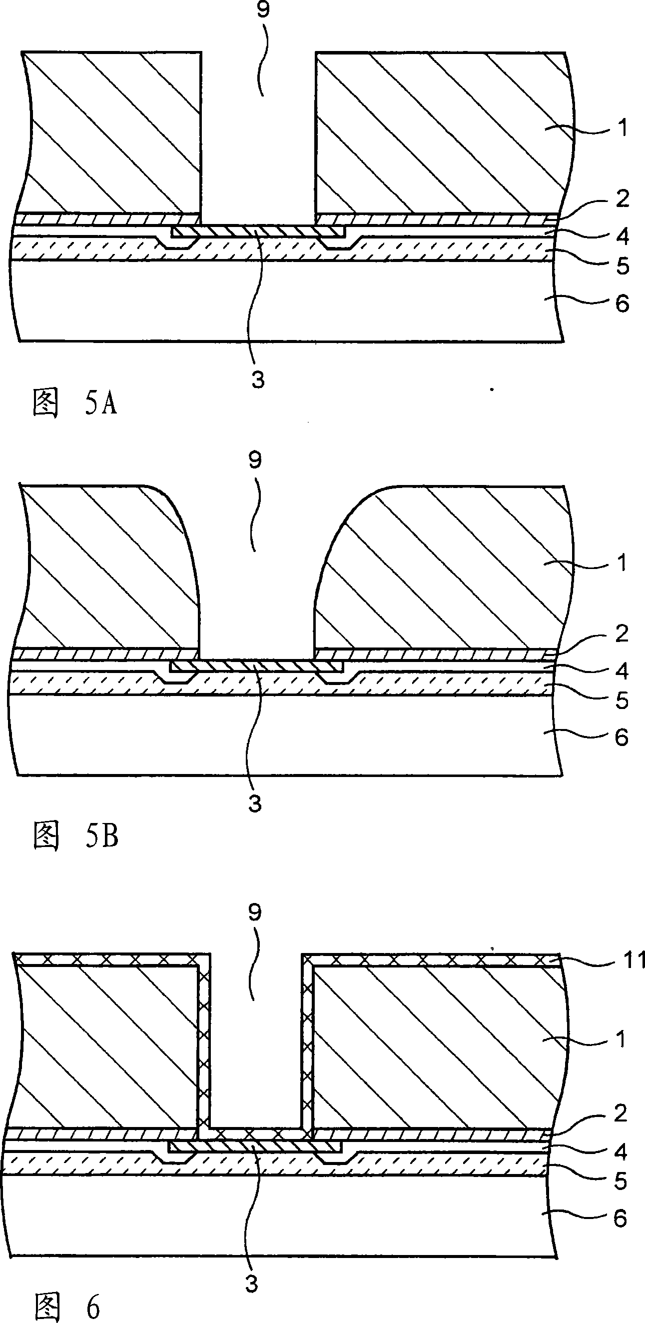
[0048] Embodiments of the present invention will be described below with reference to the drawings. 1 to 10 are cross-sectional views illustrating a method of manufacturing a semiconductor device according to an embodiment of the present invention. The manufacturing process described below is performed using a wafer-like semiconductor substrate, and a plurality of semiconductor devices are formed in a matrix with predetermined dicing lines as boundaries. However, for convenience, a process of forming a single semiconductor device will be described.

[0049] First, as shown in FIG. 1 , a semiconductor substrate 1 is prepared on which electronic devices not shown (for example, light-receiving or light-emitting elements such as CCDs or infrared sensors, or other semiconductor elements) are formed on the surface. The semiconductor substrate 1 has a diameter of, for example, 8 inches (200 mm), and a thickness of about 300 μm to 700 μm. A first insulating film 2 (for example, a sil...


PUM


Abstract

The invention provides a method of manufacturing a semiconductor device which achieves high reliability and high yield as well as high production efficiency. Back surface grinding (back grinding) is performed to a semiconductor substrate to thin the semiconductor substrate. A damaged layer formed by the back surface grinding is not removed at this time, and a photoresist layer is selectively formed on the back surface of the semiconductor substrate. The semiconductor substrate is then etched using the photoresist layer as a mask to form a via hole. The photoresist layer is then removed with the semiconductor substrate still placed in an etcher used in the etching process subsequently after the formation of the via hole. In this manner, the etching process and the next ashing process are performed sequentially in one apparatus. Then a process of removing the damaged layer on the back surface of the semiconductor substrate and a process of smoothing the sidewall of the via hole are simultaneously performed subsequently after the ashing process in the same apparatus.

Description

technical field [0001] The present invention relates to a method of manufacturing a semiconductor device, and more particularly to an etching step and a step of removing a mask layer used in the etching step. Background technique [0002] At present, when manufacturing a semiconductor device, there is an etching process in which the insulating film or metal layer of the base, or the semiconductor substrate, etc. are processed into a predetermined pattern using a resist layer as a mask, and the The ashing (ashing) process for removing the resist layer used. [0003] An example of a conventional semiconductor device manufacturing method will be described. As shown in FIG. 13( a ), the back surface of the semiconductor substrate 100 is ground (back ground) using a back grinding device (grinder), and the semiconductor substrate 100 is processed to a predetermined thickness (for example, 100 μm to 150 μm). [0004] Then, as shown in FIG. 13( b), the back surface of the semicond...

Claims


Application Information

Patent Timeline
Patent Type & Authority Applications(China)
IPC IPC(8): H01L21/3065H01L21/28
CPCH01L21/31138H01L2924/01046H01L21/76898H01L21/30655H01L2924/01078H01L21/3065H01L2924/04941H01L2924/01004H01L2924/01079H01L2924/09701H01L2224/16H01L24/05H01L2224/02372H01L2224/05008H01L2224/05009H01L2224/05025H01L2224/05147H01L2224/05164H01L2224/05166H01L2224/05181H01L2224/05184H01L2224/05186H01L2224/05548H01L2224/05568H01L2224/05569H01L2224/05644H01L2224/05655H01L2924/00014H01L2924/04953H01L2924/0496H01L2924/01074H01L2924/0494H01L21/02H01L21/302
Inventor 关克行铃木彰龟山工次郎及川贵弘
Owner SANYO ELECTRIC CO LTD
Learn More