Evaporator

An evaporator and refrigerant technology, applied in the direction of evaporator/condenser, heat exchanger shell, refrigerator, etc., can solve the problem of reduced heat exchange performance, troublesome assembly of refrigerant flow parts and separated fin parts, and sufficient discharge and other problems to achieve the effect of preventing the reduction of cooling performance

Inactive Publication Date: 2008-01-30
SHOWA DENKO KK
View PDF1 Cites 17 Cited by
  • Summary
  • Abstract
  • Description
  • Claims
  • Application Information

AI Technical Summary

Problems solved by technology

However, in the case where the amount of condensed water is large, a large amount of condensed water stagnates at this junction and cannot be sufficiently discharged from the front end side, which poses a problem that the condensed water is scattered when the air flow rate changes suddenly or the condensed water Reduced cooling performance by closing the gaps between the grids by surface tension
This creates a problem in the manufacture of the evaporator: it is cumbersome to assemble the refrigerant flow part and the separate fin part
In addition, the divided corrugated fins have a smaller heat transfer area with the air passing through the gap between the adjacent refrigerant flow parts than undivided corrugated fins, resulting in a problem of reduced heat exchange performance

Method used


Image

  • Evaporator
  • Evaporator
  • Evaporator

Examples


Embodiment 1

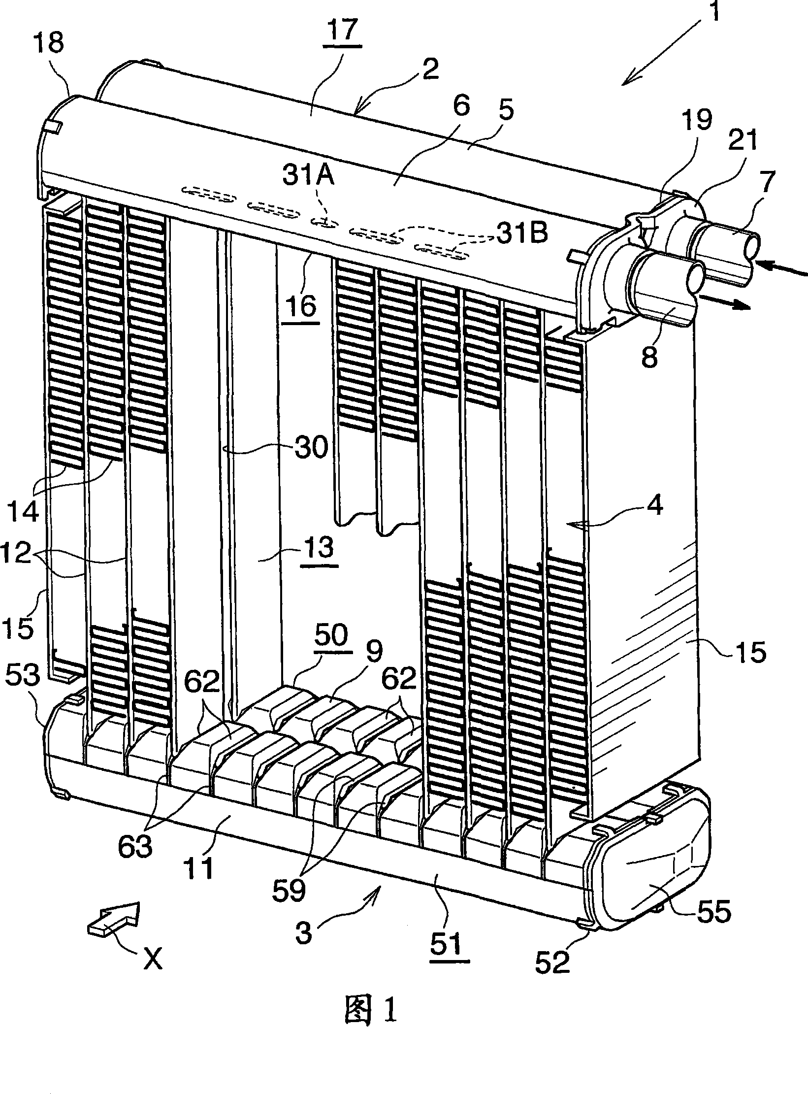
[0049] 1 to 9 show this embodiment.

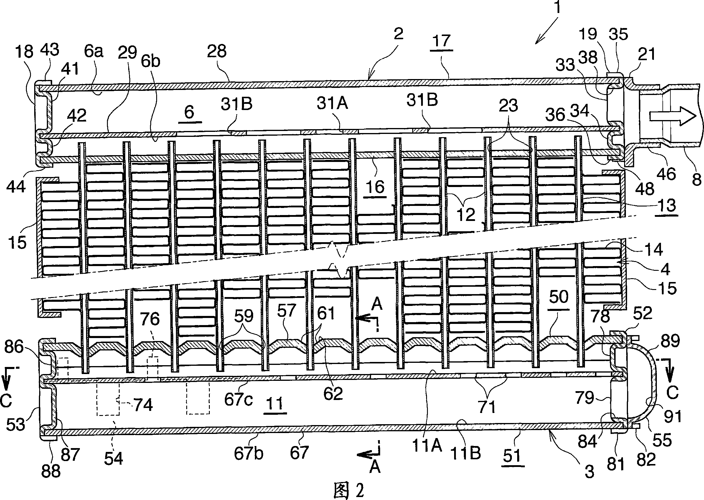
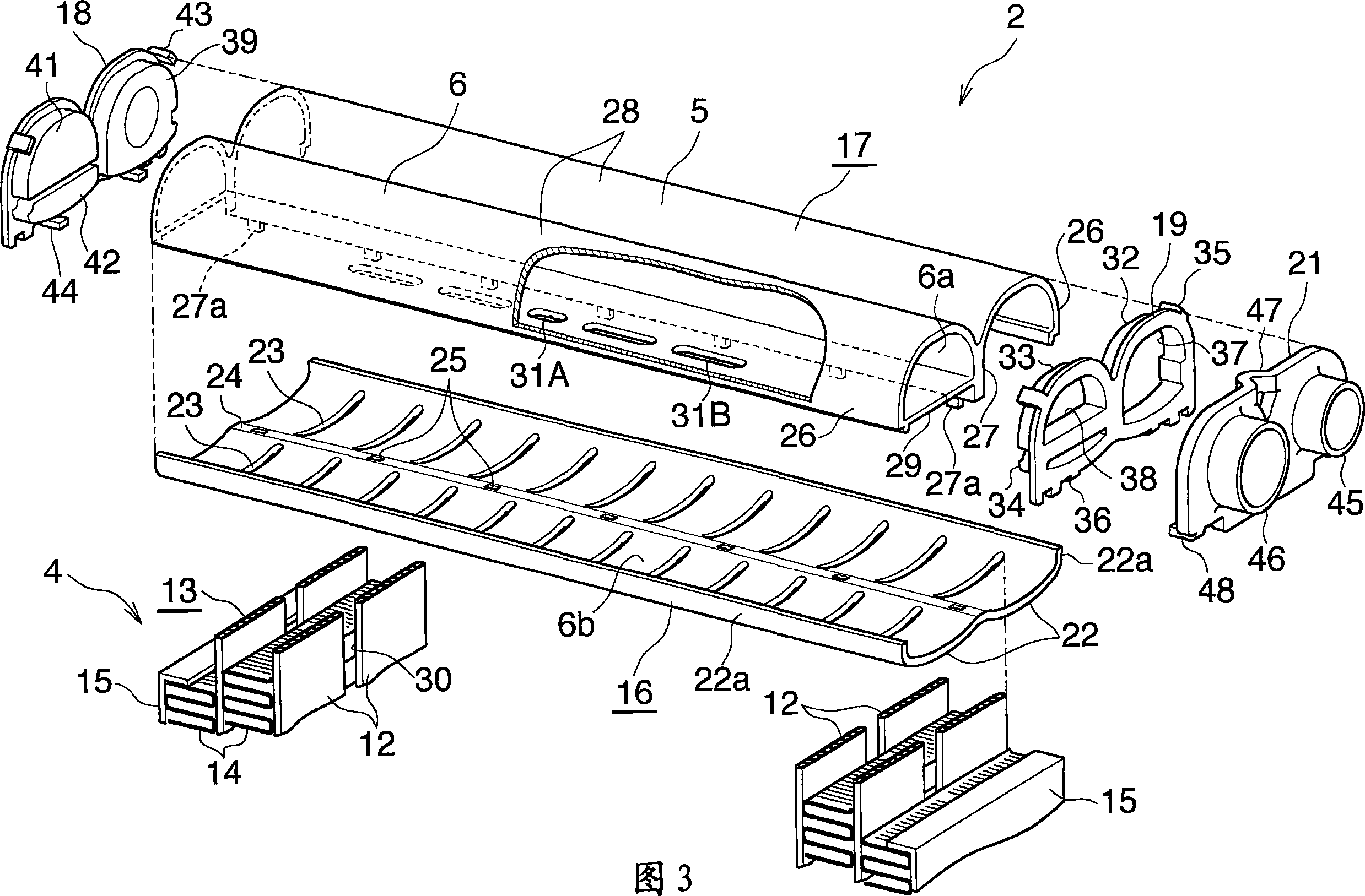
[0050] 1 and 2 show the overall configuration of the evaporator, and FIGS. 3 to 8 show the configuration of the main part of the evaporator. Figure 9 shows how the refrigerant flows in the evaporator.

[0051] In Figures 1 and 2, an evaporator (1) for a car air-conditioning unit using a chlorofluorocarbon refrigerant includes an aluminum refrigerant inlet-outlet box (2) and an aluminum refrigerant diversion box (3) , the boxes (2) and (3) are vertically separated from each other, and further include a heat exchange core (4) disposed between the boxes (2) and (3).

[0052] The refrigerant inlet-outlet box (2) includes a refrigerant inlet header portion (5) on the side toward the front (downstream side with respect to the direction of airflow) and a side toward the rear (downstream side with respect to the direction of airflow). The refrigerant outlet header (6) on the upstream side). A refrigerant inlet pipe (7) made of aluminum is conne...

Embodiment 2

[0096] This embodiment is shown in Figures 10-13.

[0097] In this embodiment, the evaporator (100) is configured such that a plurality of refrigerant flow parts (101) are stacked and combined in the left and right directions, while their widths extend in the front and rear directions (airflow direction), each of which flows The components each have a rectangular shape elongated in the vertical direction.

[0098] Each refrigerant flow part (101) includes two vertically extending rectangular aluminum plates (102) whose peripheral portions are brazed together. Each aluminum plate (102) is made of aluminum brazing sheet material having a layer of brazing material on each of its opposite sides. Two (front and rear) vertically extending, protruding refrigerant flow tube portions (103) and (104) and a protruding header forming portion (105) are provided between these two aluminum plates (102) and (106), thus partially constituting the refrigerant flow part (101). Protruding head...


PUM


Abstract

An evaporator 1 includes a plurality of refrigerant flow members 13 and corrugate fins 14 disposed in corresponding air-passing clearances between the adjacent refrigerant flow members 13. Each refrigerant flow member 13 includes a plurality of flat tubes 12 arranged in the front-rear direction. Each corrugate fin 14 is disposed to extend across all the flat tubes 12. A vertically extending drain portion 30 is formed between the flat tubes 12 adjacent each other in the front-rear direction. At each connection portion of the corrugate fin 14, a louver group 95A composed of a plurality of louvers 94A inclining downward toward the front is provided to correspond to a front portion of each flat tube 12. At least the front-end louver 94A of the louver group 95A provided to correspond to the front portion of each flat tube 12 except for the flat tube 12 at the front end is located in the drain portion 30. This evaporator exhibits excellent drainage of condensed water and enables high work efficiency in manufacture thereof.

Description

[0001] Cross References to Related Applications [0002] This application was filed pursuant to 35 U.S.C. § 111(a) and was filed under 35 U.S.C. § 111(b) on December 22, 2004 as required by 35 U.S.C. § 119(e)(1) Provisional Application No. 60 Filing date benefits of / 637,745. technical field [0003] The invention relates, for example, to evaporators to be installed in automotive air conditioning units. [0004] In the text and in the appended claims, the upper and lower sides of Figures 1, 2 and 10 will be referred to as "upper" and "lower", respectively. The downstream side of the airflow (the side indicated by the arrow X in Figures 1 and 10, and the right-hand side in Figure 4) is referred to as "front", while the opposite side is referred to as "rear". The left-hand and right-hand sides of Figures 2 and 10 are referred to as "left" and "right", respectively. Background technique [0005] A conventionally used evaporator for an automobile air conditioner includes a pl...

Claims


Application Information

Patent Timeline
Patent Type & Authority Applications(China)
IPC IPC(8): F25B39/02F28F9/02F28F1/30
Inventor 东山直久
Owner SHOWA DENKO KK
Why Eureka
Try Eureka