Thin band high speed stamping die and method for controlling oil-gas jetting

A technology of high-speed stamping and high-speed punching machine, which is applied in the field of pressure processing, can solve the problems of restricting punching speed, punching accuracy, failure to eliminate cutting edge parts in time, and material fluctuations, etc., to ensure punching accuracy, increase punching speed, The effect of avoiding damage

Inactive Publication Date: 2008-02-13
黄山三佳谊华精密机械有限公司
View PDF0 Cites 7 Cited by
  • Summary
  • Abstract
  • Description
  • Claims
  • Application Information

AI Technical Summary

Problems solved by technology

[0002] At present, in general thin-strip progressive dies, due to the extremely thin material of the stamped part, the strip is often lifted up by negative pressure and friction during the high-speed punching process. Although there is a discharge plate to force discharge and compaction, but the high-speed punching oil surface sticking force on the surface of the unloading plate will still cause the material to fluctuate with the punching stroke, which restricts the improvement of punching speed and punching accuracy. In addition, due to punching, punching The waste after cutting is easy to be blocked and collected in the die, and it is easy to damage the cutting edge parts if it cannot be removed in time

Method used


Image

  • Thin band high speed stamping die and method for controlling oil-gas jetting
  • Thin band high speed stamping die and method for controlling oil-gas jetting
  • Thin band high speed stamping die and method for controlling oil-gas jetting

Examples


Embodiment 1

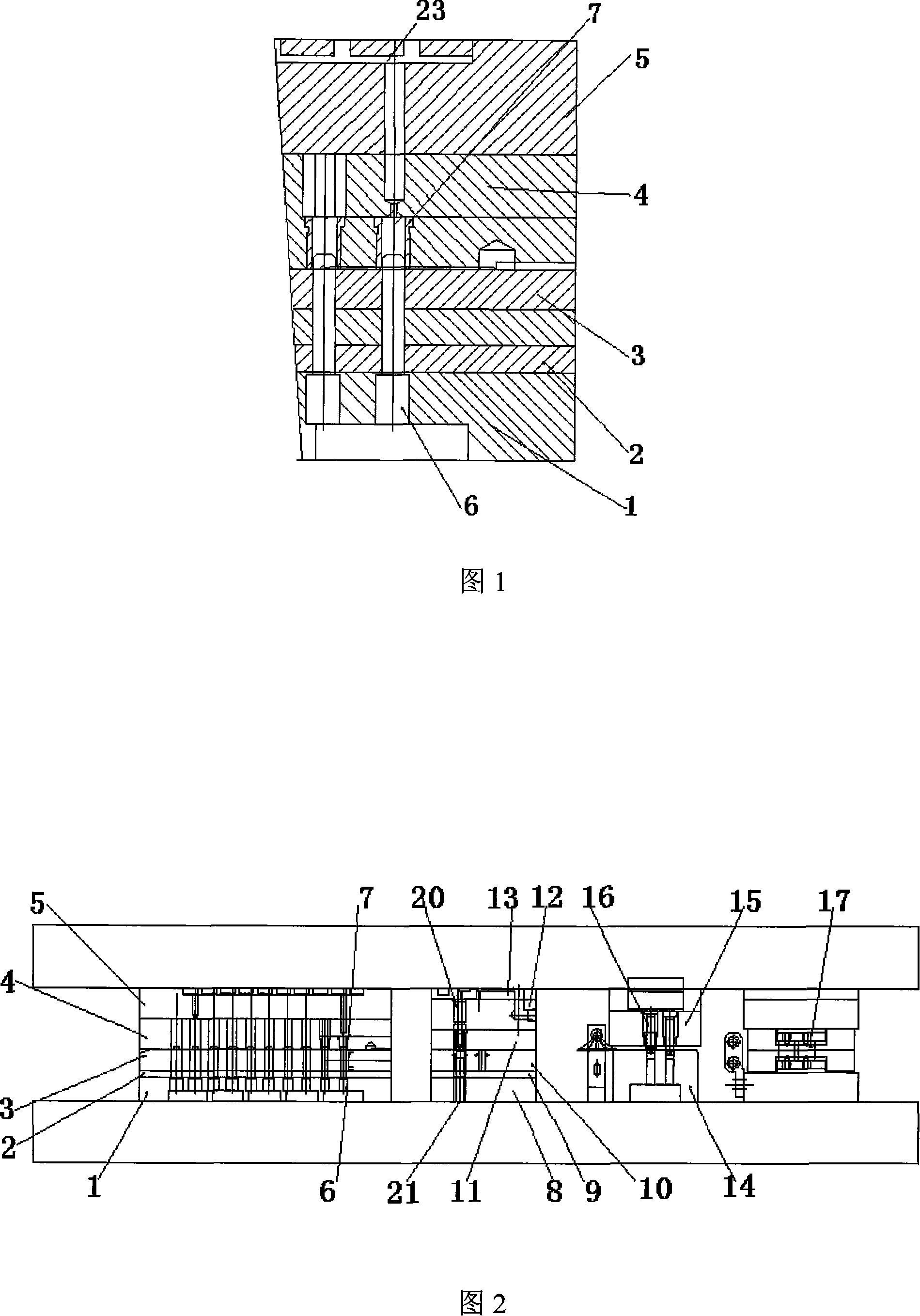
[0026] This high-speed stamping die for thin strip material provided, between the stretching die fixing plate 4 and the mold frame on the said stretching sub-mold, the stretching die is provided for the air cushion plate 5, and the stretching die fixing plate 4, the stretching Die feeder air cushion plate 5 and extension die 7 are provided with connected oil and gas passages, and the oil and gas passages of each die are collected to the extension total oil and gas passage on the drawing die feeder air cushion plate 5, and the extension total oil and gas passage is connected with the high-speed press The high-pressure oil-gas supply passage 23 of the high-pressure oil-gas supply control system is communicated with.

[0027] As shown in Figure 1, there are connected oil and gas pipelines on the extension die fixing plate 4, the extension die air cushion plate 5, and the extension die 7. Each die is uniformly and synchronously supplied with air through the extension die air cushio...

Embodiment 2

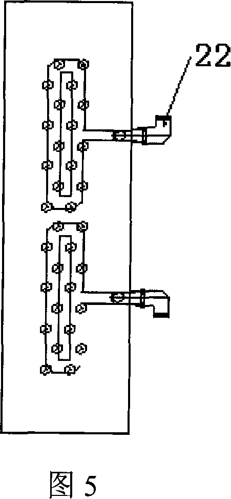
[0029] As shown in Figure 2 and Figure 5, between the punching punch fixing plate 12 and the mold frame on the punching sub-mould, a punching die is provided for the air cushion plate 13, and each punching punch 20 is fixed on the punching punch fixing plate 12 , the center of the punching punch 20 is provided with a through hole, which is the oil-gas passage, and the oil-gas passage of each punch is collected to the punching total oil-gas passage on the air cushion plate 13 of the punching die, and the punching total oil-gas passage is connected to the air-cushion plate 13. The high-pressure oil-gas supply passage 23 of the high-pressure oil-gas supply control system of the high-speed press described above is communicated.

[0030] According to the above-mentioned technical scheme, a through hole is also provided in the punching punch 20, which can be located in the center, and each punch is fixed on the punching punch fixing plate 12, and the air cushion plate 13 is uniformly...

Embodiment 3

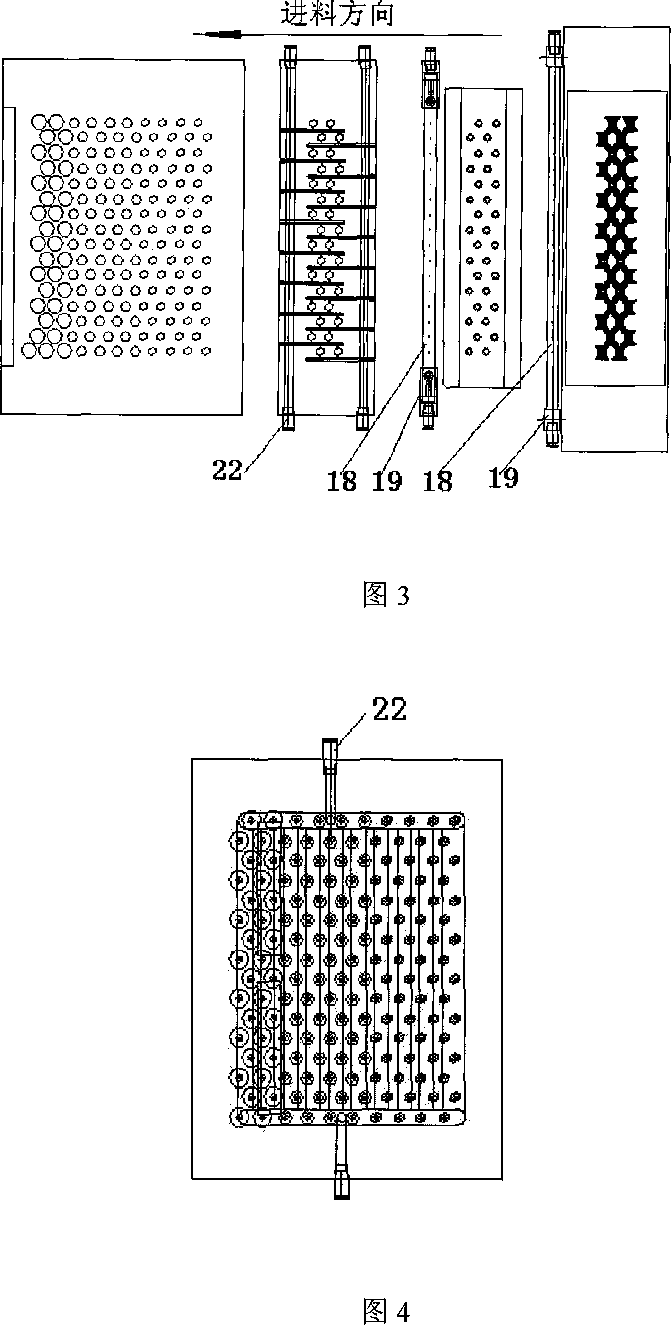
[0032] As shown in Fig. 2 and Fig. 3, a horizontal oil-air nozzle 18 for horizontal oil-gas injection is provided at the front and rear positions of the flanging sub-form, and the horizontal oil-air nozzle 18 is fixed on the oil-jet nozzle seat 19. The spray pipe 18 is evenly provided with a plurality of micropores facing the thin strip material to be punched, and the mixed oil and gas are sprayed to the surface of the thin strip material through the micropores.

[0033] In order to obtain the same effect as above, the horizontal oil and gas spray pipe 18 communicates with the high-pressure oil and gas supply passage 23 of the oil and gas supply control system of the high-speed punch press through the oil and gas pipe joint 22 arranged on the pipe, and the high pressure oil and gas is sprayed to The surface of the thin strip.

[0034] In order to make both sides of the stamped thin strip have the same effect, the method adopted by the present invention is: the horizontal oil a...


PUM


Abstract

The present invention discloses a thin belting high-speed die; every submodule in the thin belting high-speed die is equipped with a high-pressure oil gas supply closed path (23) and connected with an oil gas supply control system of a high-speed punch. An elongated die air supply supporting block (5) is equipped between an elongated concave die fixing plate (4) and a mold frame which are equipped on an elongated submodule; the elongated concave die fixing plate (4), elongated air supply supporting block (5) and elongated concave dies (7) are equipped with communicated oil gas closed paths; oil gas closed path of every concave die is gathered to an elongated common path equipped on the elongated die air supply supporting block (5) and the elongated common path is communicated with the high-pressure oil gas supply closed path 23 of the high-speed punch high-pressure oil gas supply control system. By adopting the technical proposal mentioned above, the punching speed of the thin belting is increased in the process of high-speed punching and the punching precision is ensured; the safety performance of the die is excellent which prevents the cutting edge of the punch-die from being damaged by the punching waste material.

Description

technical field [0001] The invention belongs to the technical field of pressure processing, in particular, the invention relates to a high-speed stamping die for thin strip material. In addition, the invention also relates to the oil and gas injection control method adopted by the mold. Background technique [0002] At present, in general thin-strip progressive dies, due to the extremely thin material of the stamped part, the strip is often lifted up by negative pressure and friction during the high-speed punching process. Although there is a discharge plate to force discharge and compaction, but the high-speed punching oil surface sticking force on the surface of the unloading plate will still cause the material to fluctuate with the punching stroke, which restricts the improvement of punching speed and punching accuracy. In addition, due to punching, punching The waste after cutting is easy to be blocked and collected in the die, and it cannot be removed in time, which is...

Claims


Application Information

Patent Timeline
Patent Type & Authority Applications(China)
IPC IPC(8): B21D37/10B21D37/12B21D45/00B21D37/18
Inventor 吴建军尤永贵储杰杨冬娟
Owner 黄山三佳谊华精密机械有限公司
Why Eureka
Try Eureka