Arrangement or provision of a sensor or probe for the measuring of a condition in a pipe or the like

A detector and sensor technology, applied in the field of flange joints, can solve expensive and other problems

Inactive Publication Date: 2008-02-13
NORSK HYDRO ASA
View PDF0 Cites 15 Cited by
  • Summary
  • Abstract
  • Description
  • Claims
  • Application Information

AI Technical Summary

Problems solved by technology

This known solution is expensive since a separate ring needs to be manufactured to hold the measuring device and the pressure gauge

Method used


Image

  • Arrangement or provision of a sensor or probe for the measuring of a condition in a pipe or the like
  • Arrangement or provision of a sensor or probe for the measuring of a condition in a pipe or the like
  • Arrangement or provision of a sensor or probe for the measuring of a condition in a pipe or the like

Examples


Embodiment Construction

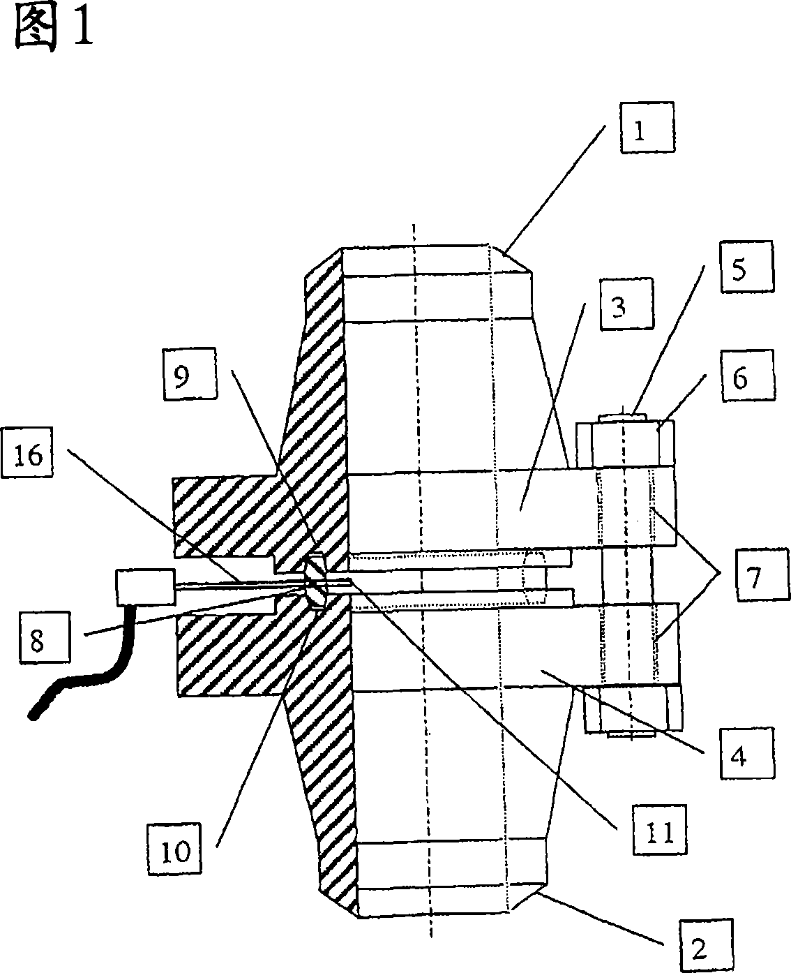
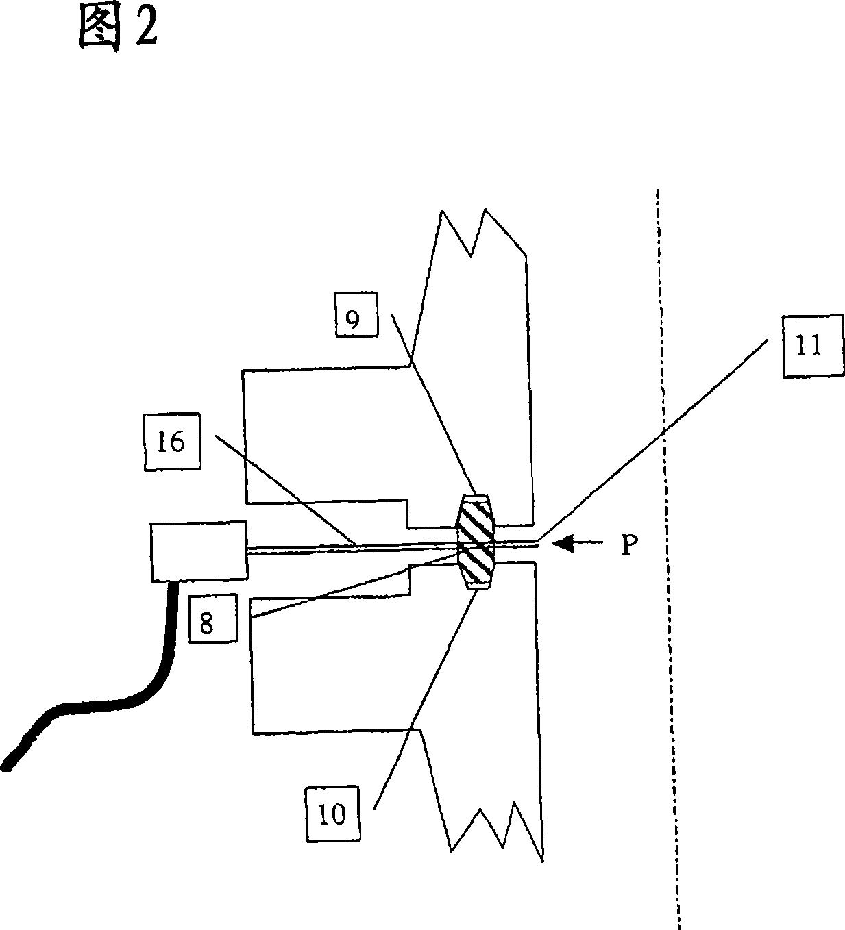
[0014] Figures 1 and 2 show the flange connection between the two pipe ends 1 and 2 described above. The flanges 3, 4 are tightly held together by bolts 5 and nuts 6 which are arranged in through holes 7 in the flanges. Annular gaskets 8 are provided between the flanges in grooves 9 and 10 in the respective flanges 3 and 4 to obtain a tight seal between the two flanges. The main inventive feature of the present application is the construction and arrangement of the sensor 11 within the gasket 8 . The sensor may be any type of sensor element that measures pressure, temperature, changes in conductivity or resistance due to corrosion or erosion of the sensor element.

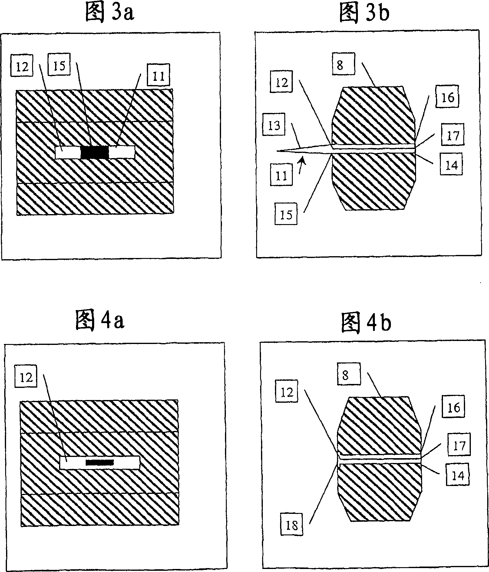
[0015] Accompanying drawing 3 a) and b) represent the figure of the gasket 8 with sensor as shown in accompanying drawing 1 and 2 on an enlarged scale, wherein a) is seen from the inner side (inner wall) of the gasket, b) is its cross-section . The sensor element 8 shown in the figure is a double-sided diaphragm...


PUM


Abstract

An arrangement or provision of a sensor or probe (11) for the measuring of a physical or chemical condition such as pressure, temperature or corrosion in a pipe (1, 2), tank or tubular container being provided with a connection such as a flange connection (3,4) between the pipe, tank or tubular sections. The sensor or probe (11) is provided in conjunction with a gasket such as a ring gasket (8) which is used as a seal between the pipe (1, 2), tank or tubular sections. The probe or sensor element is provided on an inner face of the ring gasket facing the inside of the pipe, tank or tubular sections. Electrical connectors (16) for transforming signals from the probe or sensor element (11) are provided in a bore or bores (14) that stretches from the sensor or probe and through the gasket or ring gasket (8) and to the outside of the gasket.

Description

technical field [0001] The present invention relates to a construction or arrangement of sensors or detectors for measuring physical or chemical conditions (such as pressure, temperature or corrosion) in pipes, tanks or tubular containers, in pipes, tanks or made of pipes, tanks or containers There are connecting parts in the pipe section, such as flange connecting parts. Background technique [0002] Sensors and detectors of the type described above are commonly used in the process industry to detect, monitor and control fluid flow or process conditions. Such probes or sensors are usually intrusive in that they are provided on separate measuring heads which extend through holes or boreholes in the walls of pipes, tanks or vessels and are joined by means of threads or welds attached to it. A major disadvantage of this known method is that the strength of the wall is reduced due to the opening of the wall in which the sensor or detector is located (the hole represents a poi...

Claims


Application Information

Patent Timeline
Patent Type & Authority Applications(China)
IPC IPC(8): F16L23/16G01D11/24G01K1/14G01L9/06G01L9/12G01D11/00G01D11/30G01L19/00
CPCG01K1/14G01L19/0007G01D11/30F16L23/16G01D11/245F16L2101/30
Inventor S·威格胡斯H·赫伊迈尔
Owner NORSK HYDRO ASA
Why Eureka
Try Eureka