Water desalination

a technology of desalination and water, applied in water cleaning, multi-stage water/sewage treatment, water cleaning, etc., can solve the problems of clogging of reverse osmosis medium, energy-consuming desalination by reverse osmosis, etc., and achieve the effect of avoiding any reaction

Active Publication Date: 2009-04-21
DESALN8
View PDF15 Cites 9 Cited by
  • Summary
  • Abstract
  • Description
  • Claims
  • Application Information

AI Technical Summary

Benefits of technology

[0008]The invention enables the in situ treatment of brackish or saline water derived from groundwater aquifers, surface water and the sea including seawater and brackish groundwater by application of the reverse osmosis process within the body of water which can avoid some of the problems of existing systems. The in situ treatment of the water avoids any reactions that can arise from subjecting the water to the atmosphere, sunlight and like influences.

Problems solved by technology

Desalination by reverse osmosis is energy-expensive generally, as more saline, non-potable water is pumped under pressure through a reverse osmosis medium separation chamber and aqueous solvent diffuses through the reverse osmosis medium whilst salts and contaminants are rejected by the reverse osmosis medium and concentrate in the feed stream.
This exposes the water to oxygen and sunlight which results in increased biological activity such as algal growth and physicochemical reactions such as iron oxidation and precipitation which can cause reverse osmosis medium clogging, thus water must be pretreated before desalination.

Method used


Image

  • Water desalination
  • Water desalination
  • Water desalination

Examples


first embodiment

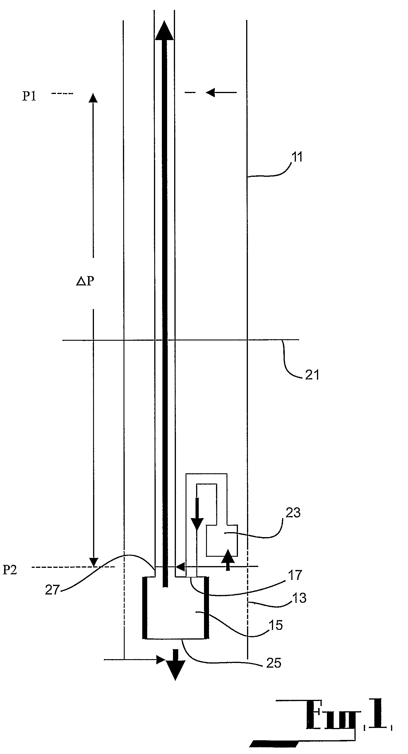
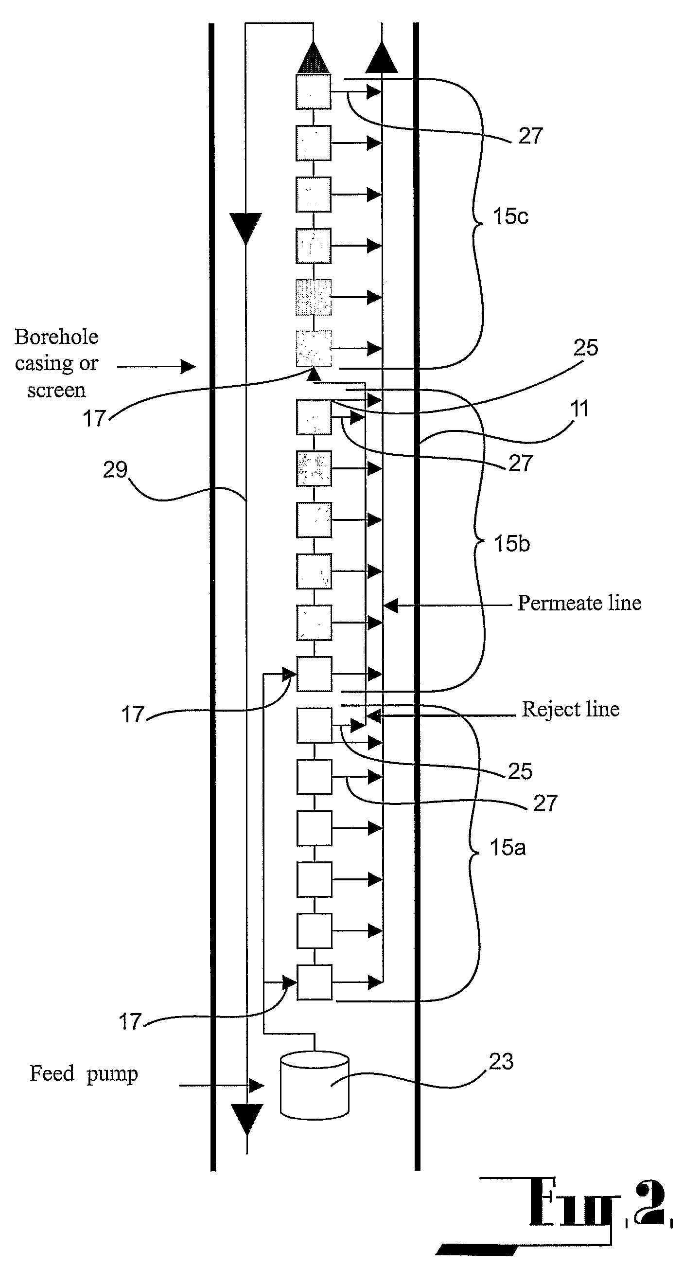
[0039]The first embodiment as illustrated at FIGS. 2 and 3 and comprises an arrangement (shown in FIG. 3) in which the inlet 17 of the reverse osmosis unit or array of units is provided with a feed pump 23 which will deliver the ground water to the inlet at a pressure greater than the inherent hydrostatic pressure at the inlet. The permeate is delivered into a storage reservoir 31 from the permeate outlet 27 and the storage reservoir is provided with a second pump 33 for extracting permeate from the storage reservoir. The storage reservoir is vented to atmosphere through a duct 35.

[0040]As shown in FIG. 2 the reverse osmosis unit 15 comprises three reverse osmosis units 15a, 15b and 15c which each comprise a set of reverse osmosis cells connected in series. The units are located longitudinally within the bore hole. The feed pump 23 delivers groundwater from the aquifer into the two lower most units 15a and 15b such that the first and second units are essentially connected in paralle...

third embodiment

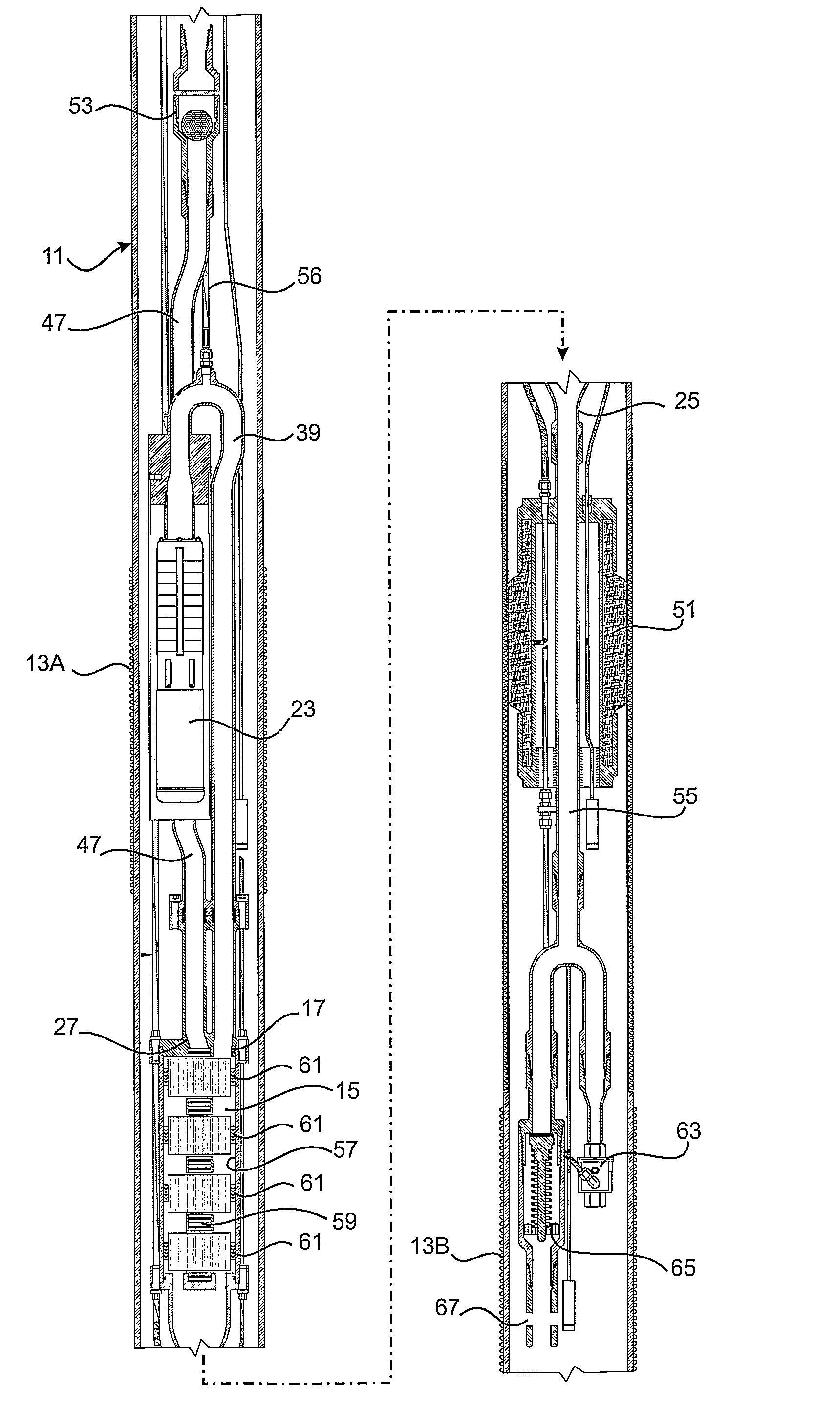
[0043]The unit is to be positioned in the borehole casing 11 which has 2 screened sections as described above. The upper screen 13A allows groundwater to enter the borehole casing when pumping starts. The lower screen 13B allows concentrate from the treatment process to be returned to the aquifer. The screens are separated by the intermediate portion of the casing, and during operation, the upper and lower screens are isolated by the inflatable packer 51. The bore annulus between the casing and the borehole and in the region of the intermediate portion is also sealed using a suitable medium such as bentonite to further isolate the influent groundwater and reinjected concentrate from the treatment plant.

[0044]The pump 23 is arranged on top of the reverse osmosis unit 15 and groundwater enters the borehole from the upper screened area 13A. The pump is installed within a pump housing which has an open end at its base. It could be possible to use a pre-filter on the pump housing if thi...


PUM

PropertyMeasurementUnit
pressuresaaaaaaaaaa
pore sizeaaaaaaaaaa
lengthaaaaaaaaaa

Abstract

An in situ desalination apparatus comprising a reverse osmosis unit (15) having a reverse osmosis medium, the reverse osmosis unit in use to be located within a body of water under ambient bio-physico-chemical conditions often different from those at the surface, the unit having an inlet (17) opening to one side of the reverse osmosis medium, in use the inlet to be located below the upper surface of a body of water, the unit having a concentrate outlet (25) opening to the one side of the reverse osmosis medium and opening into the exterior of the unit at a position spaced below the inlet to return concentrate into the water body, the unit having a permeate outlet (27) opening to the other side of the reverse osmosis medium, the permeate outlet communicating with a delivery line extending from the body of water, a pump (23) between body of water and the reverse osmosis unit and adapted to pressurize the water located at the one side of the reverse osmosis medium.

Description

CROSS REFERENCE TO RELATED APPLICATIONS[0001]This application is a 371 US National Phase of PCT / AU2005 / 000052 filed on 17 Jan. 2005, which claims priority to AU 2004900164 filed on 15 Jan. 2004.FIELD OF THE INVENTION[0002]The invention relates to desalination of brackish or saline water including seawater and groundwater by utilisation of a reverse osmosis process. The invention enables the in situ treatment of such water which can present significant advantages.BACKGROUND ART[0003]Osmotic pressure is produced when solutes in aqueous solution at one side of an osmotic reverse osmosis medium are at a chemical potential less than that in pure aqueous solvent (water) located on the other side of the reverse osmosis medium and as a result the solvent naturally permeates through the reverse osmosis medium into the aqueous solution to equalize the chemical potentials thereby exerting an osmotic pressure across the reverse osmosis medium.[0004]In reverse osmosis, pressures greater than the...

Claims


Application Information

Patent Timeline
Patent Type & Authority Patents(United States)
IPC IPC(8): E02B15/00B01D63/00C02F9/00B01D61/00B01D61/08B01D61/10B01D61/12C02F1/44
CPCB01D61/08B01D61/10B01D61/12C02F1/441C02F2103/007C02F2103/06C02F2103/08Y02W10/37Y02A20/131
Inventor BARBER, CHRISTOPHER
Owner DESALN8
Why Eureka
Try Eureka