High position wall type hanger for liquid crystal TV and computer display
A technology for LCD TVs and computers, which is applied in the field of high-position wall hangings common to LCD TVs and computer monitors. It can solve the problems of affecting the viewing effect, unconsciously reaching forward and downward, and inconvenience, etc., so as to achieve easy operation, Simple structure and ingenious effect
- Summary
- Abstract
- Description
- Claims
- Application Information
AI Technical Summary
Problems solved by technology
Method used
Image
Examples
Embodiment 1
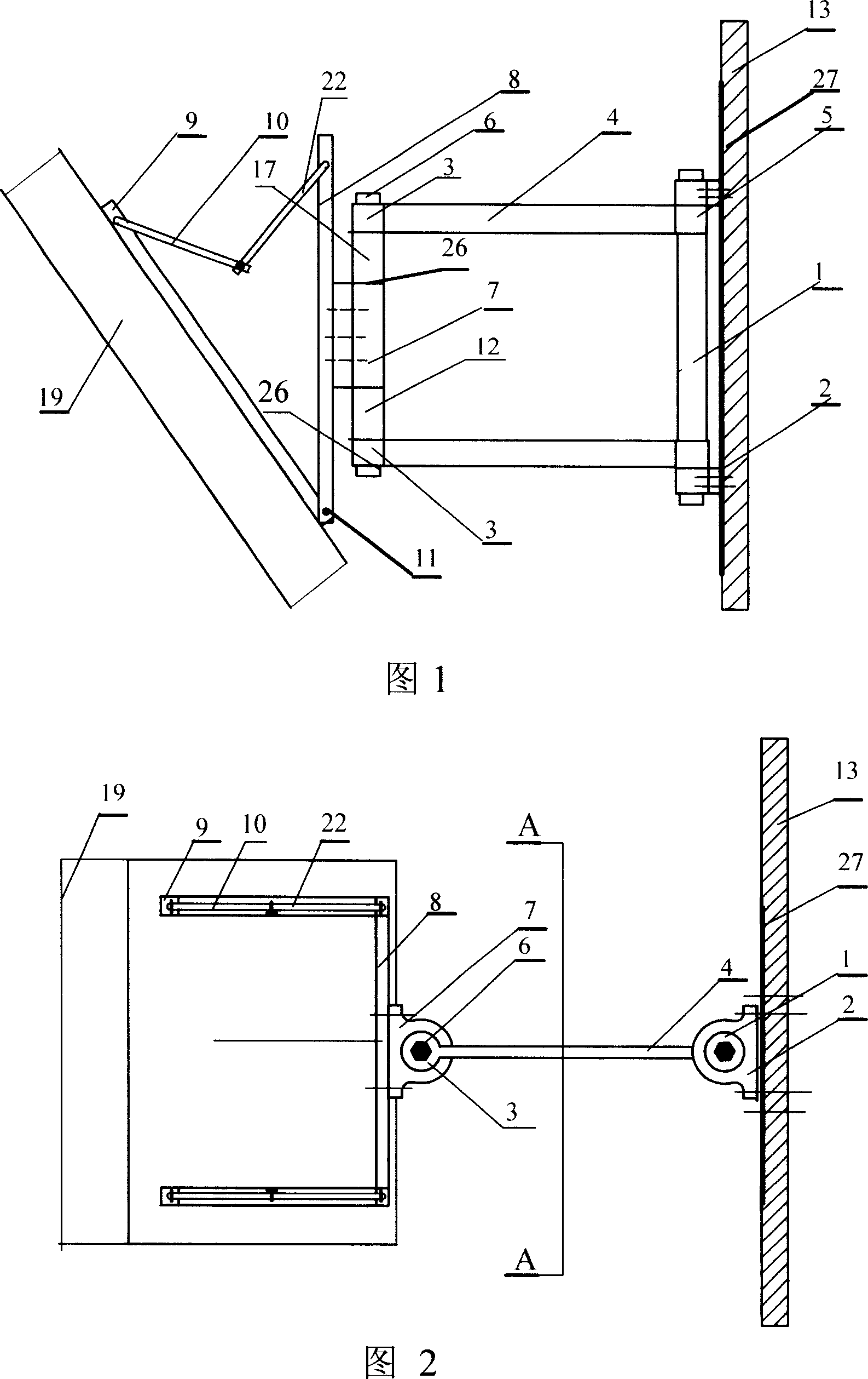
[0031] As shown in Figure 13, the common high-position wall mount for LCD TVs and computer monitors includes a support column 1, a cantilever and a rotating shaft connection mechanism, and an angle adjustment mechanism. The shaft holes 5 at one end are respectively set on the stepped shafts at both ends of the support column 1, and the support base 2 is installed on the outside of the cantilever 4 at both ends of the support column 1, and the support base 2 is fixed on the mounting plate 27, and the mounting plate 27 is installed on the wall 13. The shaft hole 3 at the other end of the cantilever 4 is sleeved on the two ends of the rotating shaft 6, and the shaft hole 3 of the cantilever 4 at the lower end is positioned by the limit card platform 12 provided on the rotating shaft 6, as shown in FIG. 12 . A sleeve 17 is installed on the top of the rotating shaft 6, and the sleeve 17 is located below the shaft hole 3 of the upper cantilever 4, and a rotating body 7 is set in the...
Embodiment 2
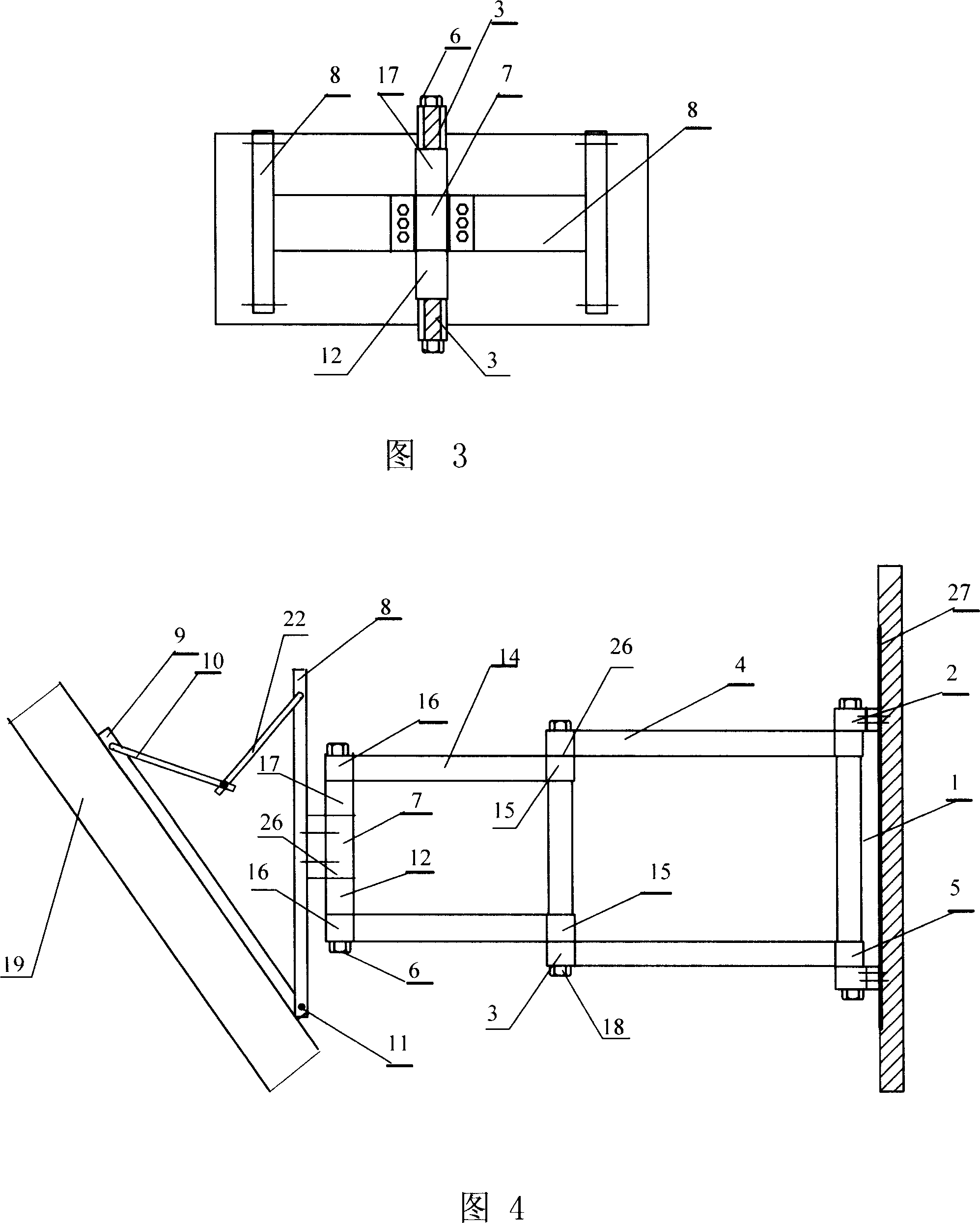
[0034] As shown in Figure 4, the second embodiment is basically the same as the first embodiment in terms of structure, the difference lies in:
[0035] The connecting mechanism between the cantilever and the rotating shaft is composed of four cantilevers, wherein the shaft holes 3 at one end of the two cantilever arms 4 are respectively set on the two ends of the connecting shaft 18, and the shaft holes 5 at the other ends of the two cantilever arms 4 are set on the support column 1 The shaft hole 15 at one end of the other two cantilevers 14 is sleeved on the two ends of the connecting shaft 18, and a wear-resistant gasket 26 is installed between the shaft hole 3 and the shaft hole 15. The shaft holes 16 at the other ends of the two cantilevers 14 are sleeved on the two ends of the rotating shaft 6 . Other connections and assemblies are the same as in Embodiment 1. The two ends of rotating shaft 6 and connecting shaft 18 are cushioned with nylon wear-resistant pads, and met...
Embodiment 3
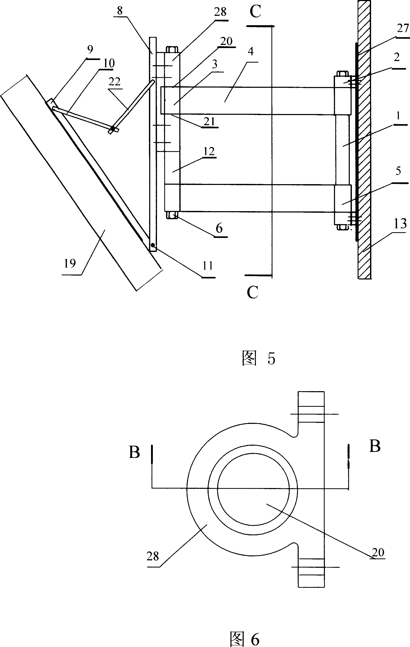
[0037] Embodiment 3 is basically the same as Embodiment 1 in structural form, the difference is that: as shown in Figure 5-8, the rotating body 28 is provided with two shaft holes 20, 21 coaxial on the upper and lower sides, and the upper and lower shaft holes The distance between 20 and 21 is equal to the length of the shaft holes 3 and 5 of the cantilever 4 . The shaft hole 3 at one end of a cantilever 4 is set on the lower end of the rotating shaft 6, positioned by the limit card platform 12 provided on the rotating shaft 6, and the rotating body 28 is set on the upper part of the rotating shaft 6, and the rotating body 28 is located on the limit card platform 12 , the other cantilever 4 shaft hole 3 is installed between the end faces of the two shaft holes 20, 21 of the rotating body 28, the rotating body 28 is connected to the middle part of the coupling bracket 8, and the other connection assembly is the same as the first embodiment . The two ends of rotating shaft 6 ar...
PUM
 Abstract
Description
Claims
Application Information
 - R&D
- Intellectual Property
- Life Sciences
- Materials
- Tech Scout
- Unparalleled Data Quality
- Higher Quality Content
- 60% Fewer Hallucinations
Browse by: Latest US Patents, China's latest patents, Technical Efficacy Thesaurus, Application Domain, Technology Topic, Popular Technical Reports.
© 2025 PatSnap. All rights reserved.Legal|Privacy policy|Modern Slavery Act Transparency Statement|Sitemap|About US| Contact US: help@patsnap.com


