Fuel-supply unit for a motor vehicle

A fuel supply and motor vehicle technology, which is applied to machines/engines, charging systems, mechanical equipment, etc., can solve problems such as short service life, high power consumption, noise, etc., and achieve the effect of simple structure and simple fuel supply

Inactive Publication Date: 2008-02-20
CONTINENTAL AUTOMOTIVE GMBH
View PDF0 Cites 5 Cited by
  • Summary
  • Abstract
  • Description
  • Claims
  • Application Information

AI Technical Summary

Problems solved by technology

Continuous operation of the transfer pump results in constant noise,

Method used


Image

  • Fuel-supply unit for a motor vehicle
  • Fuel-supply unit for a motor vehicle

Examples


Embodiment Construction

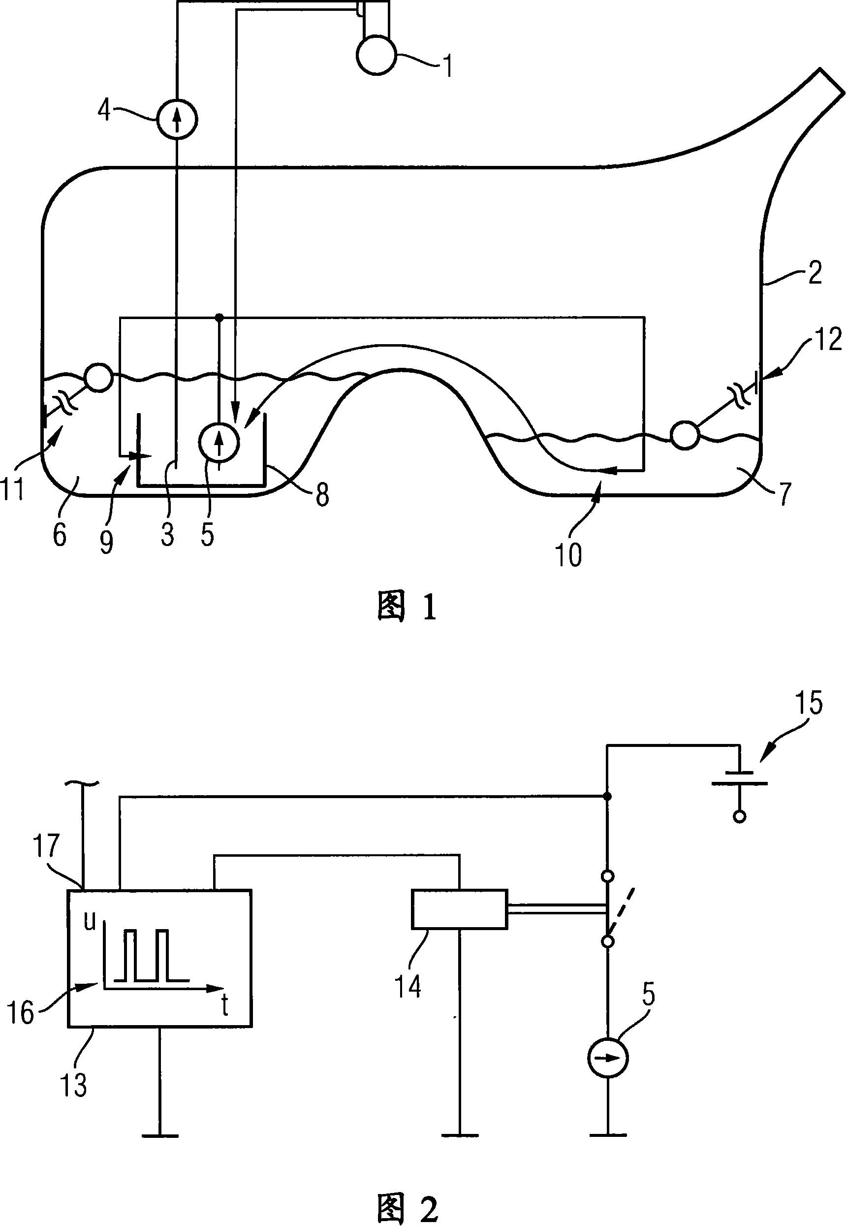
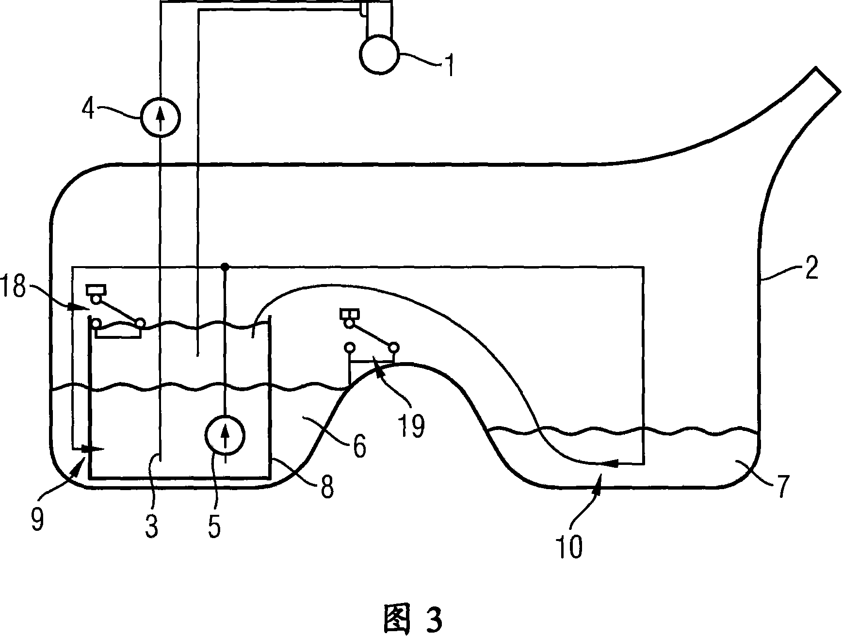
[0022] FIG. 1 schematically shows a fuel supply system for supplying fuel to an internal combustion engine 1 of a motor vehicle operating on the diesel principle. The fuel supply device has a main fuel pump 4 and a delivery pump 5 that sucks fuel through a suction connection 3 protruding into the fuel tank 2, and the delivery pump delivers the fuel in the fuel tank 2 to the suction of the main fuel pump 4. Oil joint 3. The main fuel pump 4 can be, for example, a mechanically driven high-pressure diesel pump. The fuel tank 2 is designed as a so-called saddle tank with two chambers. The main fuel pump 4 is arranged outside the fuel tank 2 , while the suction connection 3 and the delivery pump 5 are arranged inside a swirl box 8 preloaded to the bottom of the fuel tank 2 . Arranged in the chambers 6 , 7 are ejector pumps 9 , 10 which are supplied with fuel as drive medium by the delivery pump 5 and which convey the fuel from the chambers 6 , 7 into the swirl box 8 . Furthermor...


PUM


Abstract

The invention relates to a fuel-supply unit for a motor vehicle, comprising a fuel container (2) that has several chambers (6, 7). Said unit comprises a transfer pump (5) that is located inside the fuel container (2) for exclusively supplying ejector pumps (9, 10), which are positioned in the chambers (6, 7), with fuel as the pumping fluid. A primary fuel pump (4) that is located outside the fuel container (2) supplies an internal combustion engine (1) of the motor vehicle with fuel. The transfer pump (5) is operated discontinuously to prevent unnecessary power consumption.

Description

technical field [0001] The invention relates to a fuel supply system for a motor vehicle having a fuel tank and a main fuel pump arranged outside the fuel tank for drawing fuel from the fuel tank and supplying the fuel to an internal combustion engine. Background technique [0002] Such fuel pumps are frequently installed in today's motor vehicles together with single chamber fuel tanks and are well known in practice. In today's fuel supply systems, the fuel not required by the internal combustion engine is often fed back into the fuel tank without pressure. Therefore, an ejector pump, which conveys fuel from the secondary chamber of the fuel tank to the main chamber, must not be connected in the return line. However, fuel tanks with multiple chambers are often used in all wheel drive vehicles. [0003] It has already been considered to install a transfer pump for feeding the ejector pump provided in the fuel tank. The continuous operation of the delivery pumps results in...

Claims


Application Information

Patent Timeline
IPC IPC(8): F02M37/10F02M37/02F02M37/18
CPCF02M37/106F02M37/025F02M37/18Y10T137/86083F02M37/02F02M37/10
Inventor 贝恩德·伦普夫
Owner CONTINENTAL AUTOMOTIVE GMBH
Why Eureka
Try Eureka