Sealing type compressor

A compressor, sealed technology, applied in the direction of compressors, refrigerators, mechanical equipment, etc., can solve the problems of large oil level agitation, oil transition splash, etc., to reduce noise, size, and oil splash. Effect

Inactive Publication Date: 2008-02-27
SAMSUNG GWANGJU ELECTRONICS CO LTD
View PDF0 Cites 1 Cited by
  • Summary
  • Abstract
  • Description
  • Claims
  • Application Information

AI Technical Summary

Problems solved by technology

[0008] However, in this conventional hermetic compressor, the center of the lower end of the absorbing portion 4b of the above-mentioned oil absorbing member 4 is located outside the shaft core C of the rotating shaft 1, so when the rotating shaft 1 rotates, the absorbing portion 4b of the oil absorbing member 4 opposes the oil surface. The problem of too much churn
[0009] In addition, when the oil absorbing member 4 rotates, a vortex having a shape corresponding to the shape outside the absorbing portion 4b is formed on the oil surface on the outside of the absorbing portion 4b. However, the oil absorbing member 4 of this conventional hermetic compressor is arranged as Since it protrudes outward to have a predetermined curvature, there is a problem that the vortex formed outside the absorbing portion 4b becomes larger corresponding to the portion protruding outward in this way.
[0010] Thereby, because of the structure of this oil-absorbing member, this hermetic compressor has the following problems, that is, when the oil-absorbing member performs oil-absorbing action, the machine oil on the oil surface of the machine oil is excessively splashed and a large vortex is formed, thereby causing 4-5KHz vibration. loud noise

Method used


Image

  • Sealing type compressor
  • Sealing type compressor
  • Sealing type compressor

Examples


Embodiment Construction

[0020] Hereinafter, the preferred embodiments according to the present invention will be described in detail with reference to the accompanying drawings.

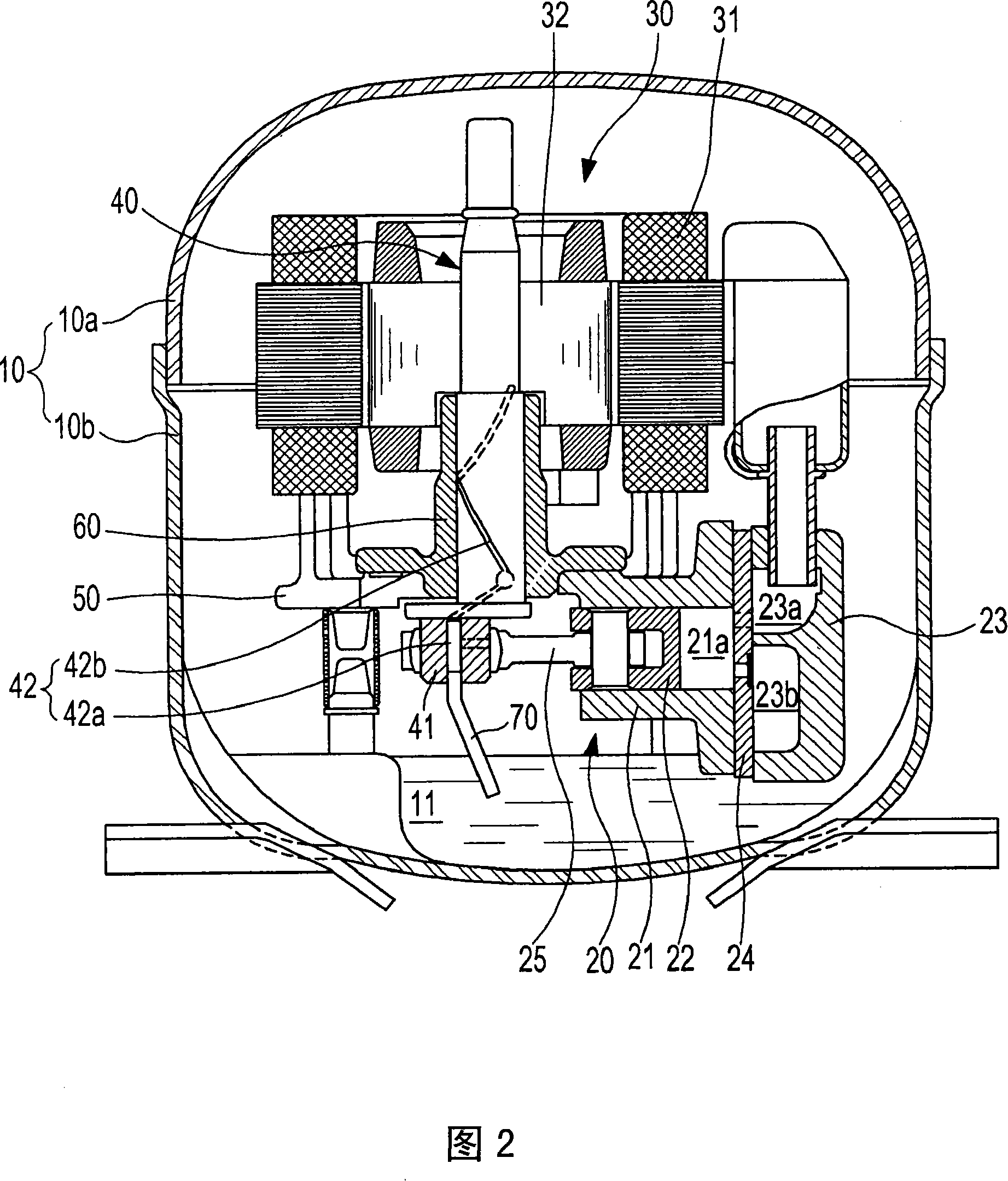
[0021] As shown in FIG. 2, the compressor according to this embodiment includes: a sealed container 10, which is formed by combining an upper container 10a and a lower container 10b; Performing compression; a driving unit 30 that provides compression driving force for compressing the refrigerant; and a rotating shaft 40 that connects the driving unit 30 and the compression unit 220 to transmit the driving force of the driving unit 30 to the compression unit 20.

[0022] The drive unit 30 and the compression unit 20 are installed inside the sealed container 10 through a frame 50. First, the drive unit 30 includes a stator 31 fixed to the upper housing side of the frame 50; and a rotor 32 on the stator The inside of 31 is spaced apart, and it rotates by electromagnetic interaction with stator 31. Here, the above-mentioned rotatin...


PUM


Abstract

The sealed compressor of the invention comprises the following components: a driving unit which is arranged at the inner side of the sealed container that is formed with an engine oil storing space at the bottom surface; a compressing unit which receives the driving force of the driving unit and do compression to the cryogen; a rotating shaft which transfers the driving force of the driving unit to the compressing unit and guides the engine oil in the engine oil storing space to the tucking part of the compressing unit and the driving unit; an eccentric shaft part which is arranged eccentrically at the lower end of the rotating shaft; and an oil sucking component which is connected to the lower end of the eccentric shaft in order to suck the engine oil in the engine oil storing space to the engine oil flow circuit, the oil sucking component comprises the following components: a press-in part which is arranged parallel to the length direction of the rotating shaft with the mode that the press-in part is combined with the eccentric shaft part; and an absorbing part which sustains a straight lien shape between the upper end and the lower end, and bends from the lower bending of the press-in part according to the mode that the center of the lower end and the axle core of the rotating shaft are consistent.

Description

Technical field [0001] The present invention relates to a hermetic compressor, and more particularly, to a hermetic compressor configured to effectively reduce noise generated by oil pick-up by improving the structure of an oil pick-up member of the hermetic compressor. Background technique [0002] Generally, a hermetic compressor used in a refrigerating cycle device such as a refrigerator or an air conditioner has an appearance by forming a sealed container with an organic oil storage space on the bottom surface. [0003] A drive unit that provides compression driving force of the refrigerant and a compression unit that receives the drive force from the drive unit and performs the compression action of the refrigerant are arranged inside the sealed container. The drive force of the drive unit is transmitted to the compressor through the rotating shaft. unit. [0004] The rotating shaft is provided with its upper part pressed into the rotor of the drive unit. The compression uni...

Claims


Application Information

Patent Timeline
IPC IPC(8): F04B39/02
CPCF04B9/045F04B35/04F04B39/0027F04B39/023F04B39/0246F05B2260/962F25B31/02F25B2500/12Y10S417/902
Inventor 金善万金春植朴硕勋李成鲁
Owner SAMSUNG GWANGJU ELECTRONICS CO LTD
Why Eureka
Try Eureka