
Natural gas liquid charging-up pump and natural gas liquid charging-up station

A liquefied natural gas, filling pump technology, applied in the direction of pumps, pump devices, pump components, etc., can solve the problems of frequent maintenance, failure, etc., to prevent cavitation, simplify the manufacturing process, improve work stability and reliability. Effect

Inactive Publication Date: 2008-02-27
林寿贵
View PDF1 Cites 6 Cited by
  • Summary
  • Abstract
  • Description
  • Claims
  • Application Information

AI Technical Summary

Problems solved by technology

[0005] However, the disadvantages of this liquefied natural gas filling station are also obvious. People like to choose the submersible pump with mature manufacturing technology as the power source when filling liquid, which can reduce the cost, but the structure of the traditional submersible pump is not Not specially designed for pumping liquefied petroleum gas, so it often breaks down in use and requires frequent maintenance

Method used


Image

  • Natural gas liquid charging-up pump and natural gas liquid charging-up station
  • Natural gas liquid charging-up pump and natural gas liquid charging-up station

Examples


Embodiment 1

[0022] (Embodiment 1, liquefied natural gas filling pump)

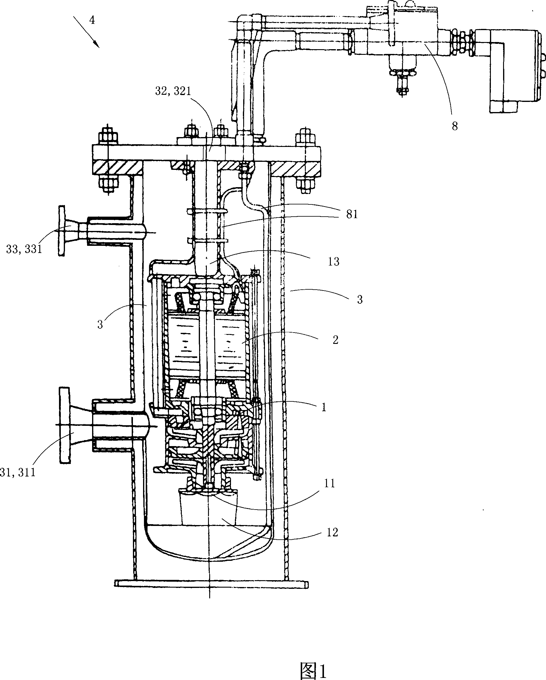
[0023] As shown in Fig. 1, this embodiment is a liquefied natural gas filling pump, which has a circuit controller 8, a vertically arranged casing 3, a pump main body 1 arranged in the casing 3, and an impeller 11 that drives the rotation of the impeller 11 in the pump main body 1. The motor 2 and the circuit controller 8 are connected to the motor 2 through a wire 81; the pump body 1 is provided with a suction port 12 and a pressure outlet 13; the suction port 12 of the pump body 1 is arranged at the bottom of the pump body 1, and the pressure port 13 is set on the top of the pump main body 1, and the suction port 12 of the pump main body 1 is also provided with a deflector for avoiding cavitation; the housing 3 is provided with a liquid inlet 31, a liquid outlet 32 ​​and an air return port 33 ; The liquid outlet 32 ​​communicates with the pressure outlet 13 of the pump main body 1 through a pipeline. The height of ...

Embodiment 2

[0025] (Example 2, liquefied natural gas filling station)

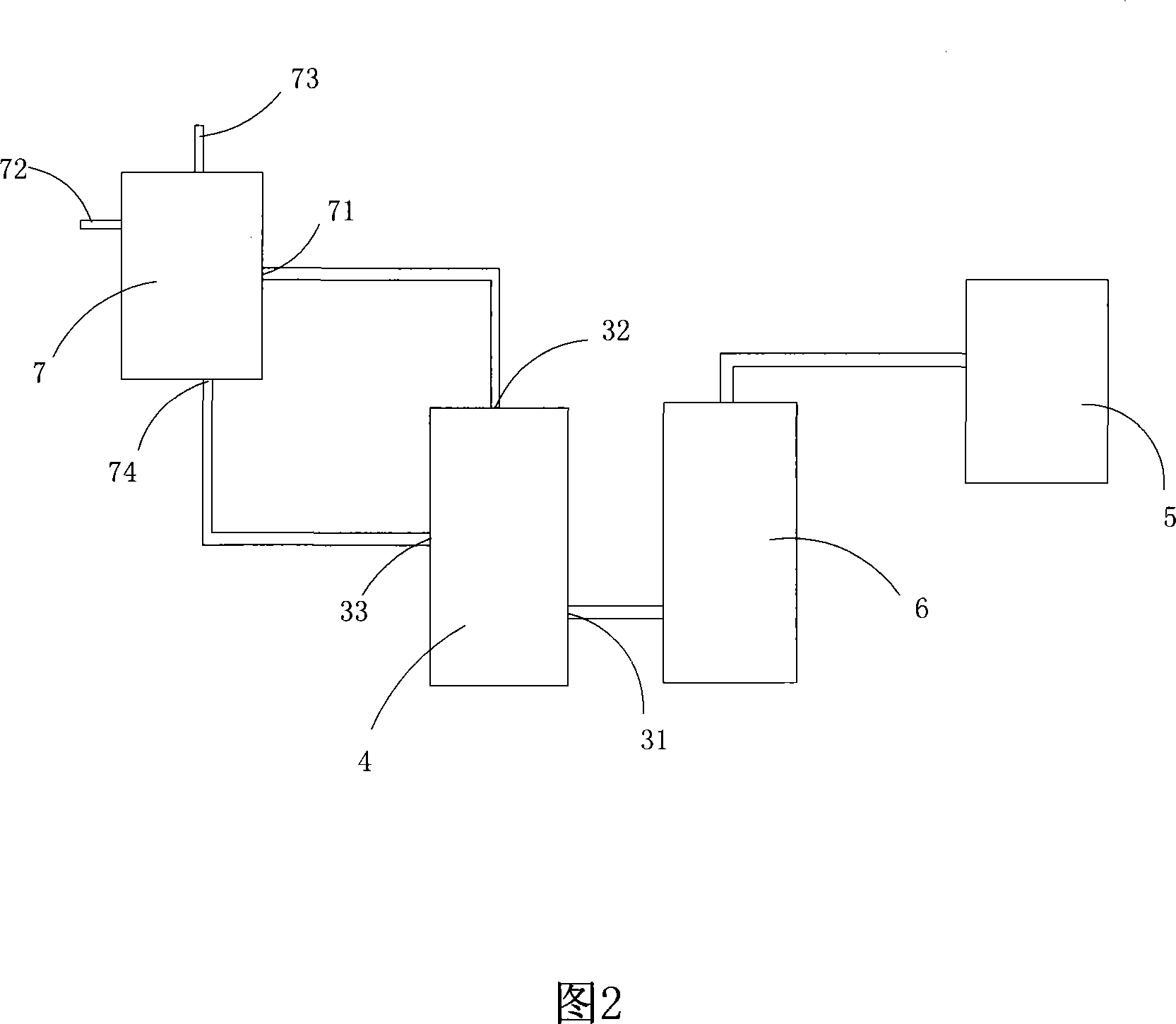
[0026] As shown in Fig. 2, this embodiment is a LNG filling station formed by using the LNG filling pump 4 of Embodiment 1, including an unloading device 5 for unloading the LNG in the LNG tanker to the natural gas storage tank 6 , liquefied natural gas storage tank 6, liquefied natural gas filling pump 4 and LNG filling machine 7. The unloading equipment in this embodiment is an electric centrifugal pump; in other embodiments, a crane can also be used to directly unload the on-board gas storage tank of the LNG tanker; the liquefied natural gas filling pump 4 has a housing 3, and The pump main body 1 arranged in the housing 3 and the motor 2 that drives the impeller 11 in the pump main body 1 to rotate, the pump main body 1 is provided with a suction port 12 and a pressure outlet 13; the housing 3 is provided with a liquid inlet 31 , a liquid outlet 32 ​​and an air return port 33; the liquid outlet 32 ​​communicates ...


PUM


Abstract

The present invention discloses one kind of liquefied natural gas filling pump and corresponding liquefied natural gas filling station. The filling pump has one pump body with one sucking port and one pressing out port and one motor to drive the vane wheel inside the pump body to rotate, and features its shell for housing the pump body and the motor and with one liquid inlet, one liquid outlet communicated through pipeline to the pressing out port in the pump body, and one gas returning port. The liquefied natural gas filling station includes one unloading unit, one liquefied natural gas storage tank, one liquefied natural gas filling pump and one liquefied natural gas filling machine connected serially. The present invention has the advantages of operation stability and high reliability.

Description

technical field [0001] The invention belongs to the technical field of automobile fuel filling, and in particular relates to a liquefied natural gas filling pump and a liquefied natural gas filling station. Background technique [0002] Liquefied natural gas, referred to as LNG, is a clean vehicle fuel and can also be used as industrial fuel or chemical raw material. The role of the liquefied natural gas filling station is to fill the liquefied natural gas into the fuel tank of the motor vehicle at a pressure of 0.52-0.83MPa. [0003] The existing liquefied natural gas filling station includes unloading equipment, liquefied natural gas storage tanks, centrifugal pumps with good sealing performance and LNG filling machines connected in series. [0004] The manufacturing technologies for unloading equipment, wildflower natural gas storage tanks, submersible pumps and LNG filling machines used in the construction of liquefied natural gas filling stations are relatively mature,...

Claims


Application Information

Patent Timeline
IPC IPC(8): F04D13/06F04D29/42F04D29/44F17C5/02
Inventor 林寿贵
Owner 林寿贵
Learn More