DDS signal generator and waveshape memory depth control method thereof

A signal generator and waveform storage technology, applied in digital function generators, automatic power control, electrical components, etc., can solve problems such as waste, inability to use storage space, and inability to meet storage requirements, and achieve the goal of reducing phase noise Effect

Active Publication Date: 2008-02-27
RIGOL
View PDF0 Cites 11 Cited by
  • Summary
  • Abstract
  • Description
  • Claims
  • Application Information

AI Technical Summary

Problems solved by technology

Moreover, for arbitrary waveforms, the internal waveform storage space provided by the DDS signal generator for users is a fixed-length waveform storage space. For arbitrary waveforms whose waveform sampling points are less than this length, a storage space has to be occupied, which is very important. wasteful
However, for arbitrary waveforms larger than this length, they cannot be stored in one storage space, which causes a huge waste of storage space due to the inability to utilize the remaining storage space, and cannot meet the storage requirements for arbitrary waveforms of different lengths.

Method used


Image

  • DDS signal generator and waveshape memory depth control method thereof
  • DDS signal generator and waveshape memory depth control method thereof
  • DDS signal generator and waveshape memory depth control method thereof

Examples


Embodiment 1

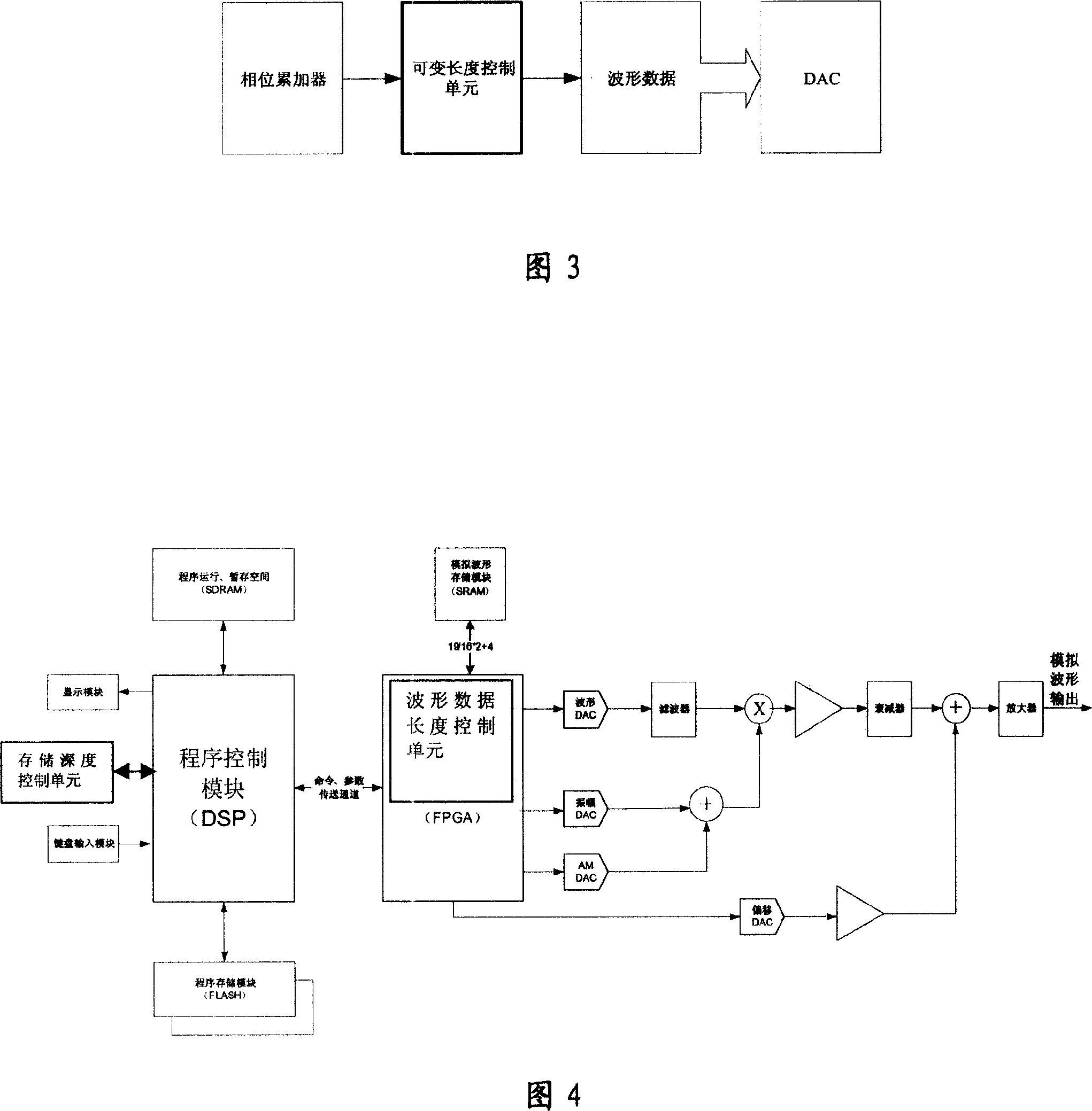
[0022] The present invention provides a DDS signal generator waveform storage depth control method, as shown in Figure 2, a variable length control unit is set in the common DDS signal generator, the variable length control unit is located in the common DDS signal generator Between the frequency synthesis unit and the waveform memory, used to control the access control of the frequency synthesis unit to the waveform memory.

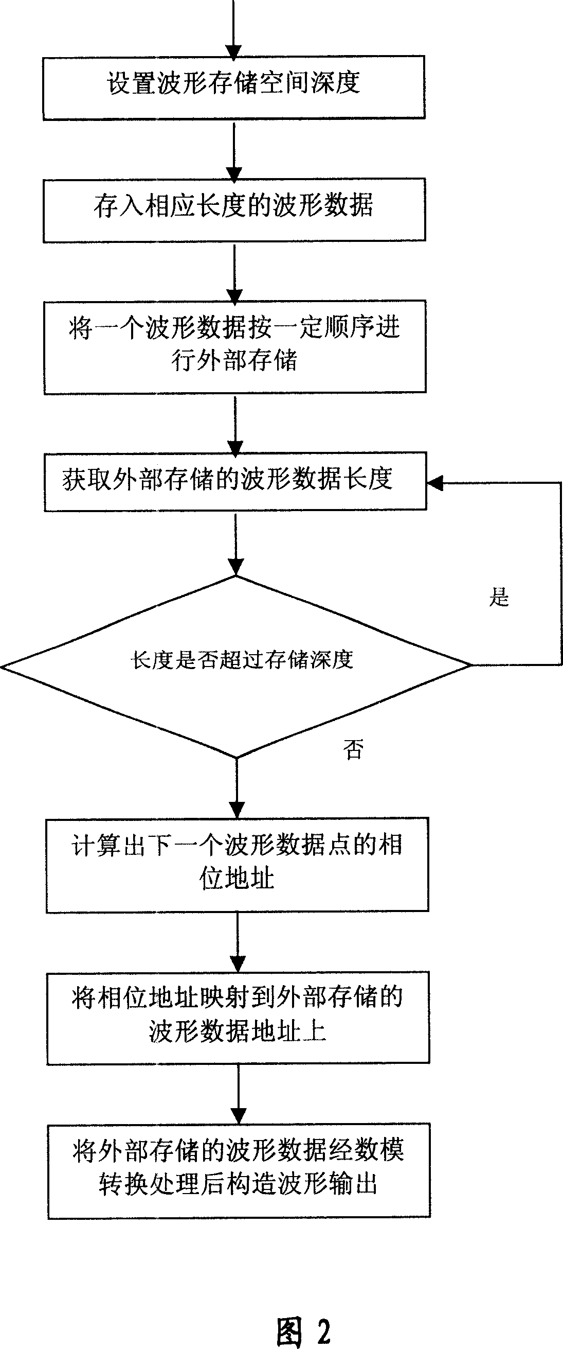
[0023] First, the waveform depth is downloaded to the storage depth control unit through the man-machine interface. The storage control unit intercepts the read request of the frequency synthesis unit to the waveform memory. Once the waveform request is found to exceed the set storage depth, it will roll back to the waveform memory. The beginning of the read waveform point. The specific steps are (as shown in Figure 3): set the depth of the waveform storage space according to the length of the waveform data, and store the waveform data into the waveform s...

Embodiment 2

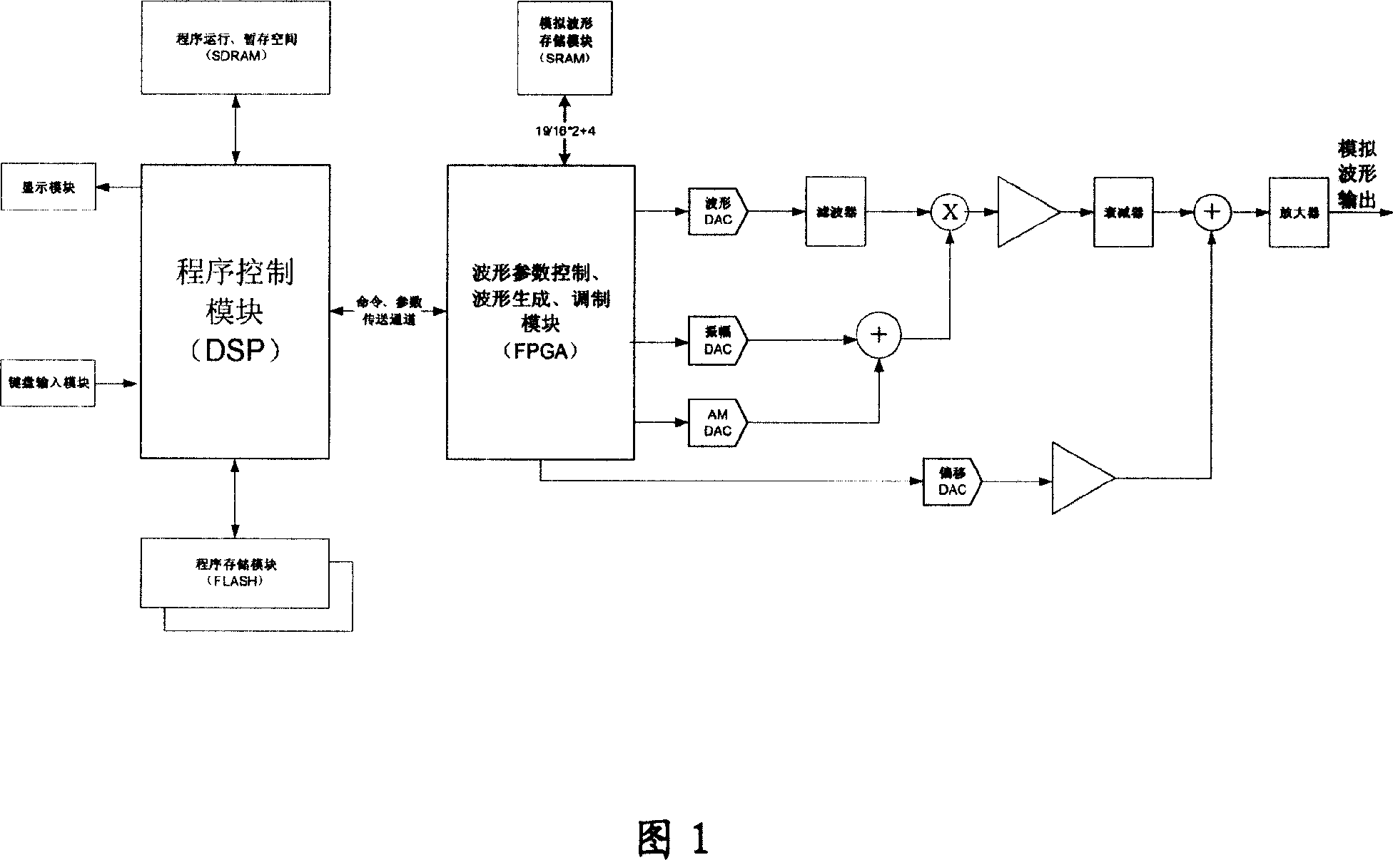
[0026] The invention provides a DDS signal generator. As shown in Figure 4, the digital signal processing (DSP) chip is used as the control device, the flash memory (FLASH) is used as the waveform memory, the field programmable gate array (FPGA) is used as the waveform processing device, and the analog unit still uses a common DDS signal generator In the digital-to-analog conversion and simulation part, the keyboard is used as the human-machine interface device and the liquid crystal display (LCD) is used as the display device; the DSP is connected with the FPGA, the keyboard and the LCD respectively, and the FPGA is connected with the analog unit.

[0027] A storage depth control unit is integrated in the DSP, which is used to control FLASH to store waveform data of corresponding length according to the storage space depth set by the keyboard;

[0028] SRAM is used as the external memory, and the SRAM is connected to the FPGA to store a waveform data in the FLASH in a certain...


PUM


Abstract

This invention is a sort of DDS signal generator and control method of wave storage deepness, the space deepness of wave storage is set according to the wave data length, and it makes the wave data to be deposited to the wave storage space of the corresponding deepness. A wave data of this wave storage space progresses the exterior storage according to the stated order. It obtains the wave data length of the exterior storage. It accumulates the wave data length of the next wave data point according to the corresponding position of the initiative wave data point of the wave data of the exterior storage. It mappings this corresponding address to the wave data address of the exterior storage according to this wave data length. It makes the wave data of the exterior storage to be structured to the wave by the digifax transition and exports it. It is used for restructuring a sort of control mechanism of the storage deepness that it does not work the wave distortion and it makes the best of the storage deepness according to the quantity of the random wave sampling point. It not only satisfies the request of the storage of the more shortwave but also the long wave.

Description

technical field [0001] The present invention relates to signal generator technology, in particular to the control of waveform storage depth of Direct Digital Frequency Synthesis (DDS: DirectDigital Frequency Synthesis) signal generator, specifically a DDS signal generator and its waveform storage depth control method. Background technique [0002] As shown in Figure 1, the overall architecture of a DDS signal generator generally includes a man-machine interface, a waveform memory, a frequency synthesis unit, a waveform control unit and an analog unit. The waveform memory stores the sampling points within a waveform period; the frequency synthesis unit generates different waveform phase transformation points according to the frequency setting, and extracts the sampling point amplitude of the corresponding phase from the waveform memory; the waveform control unit controls the amplitude of the waveform. Offset and other related parameters; the analog unit reconstructs the sampl...

Claims


Application Information

Patent Timeline
Patent Type & Authority Applications(China)
IPC IPC(8): G06F1/03H03L7/00
Inventor 王悦王铁军李维森
Owner RIGOL
Why Eureka
Try Eureka