Method for optimizing cockpit support structures

A supporting structure and cockpit technology, applied in superstructure, design optimization/simulation, superstructure subassembly, etc., can solve problems such as hindering the development process, uneven edges and installation space

Inactive Publication Date: 2008-02-27
SIEMENS VDO AUTOMOTIVE AG (DE)
View PDF0 Cites 2 Cited by
  • Summary
  • Abstract
  • Description
  • Claims
  • Application Information

AI Technical Summary

Problems solved by technology

The problem here is that when the requirements are not met, a remodel or redesign is required, especially when the flaw is recognized at a very late point in the design, greatly hindering the development process
The problem here in the area of ​​the cockpit of the vehicle is that, during iterations, installation spaces with ragged edges (or cracked zerklüftet) can arise in the area between the vehicle body and cockpit components

Method used


Image

  • Method for optimizing cockpit support structures
  • Method for optimizing cockpit support structures
  • Method for optimizing cockpit support structures

Examples


Embodiment Construction

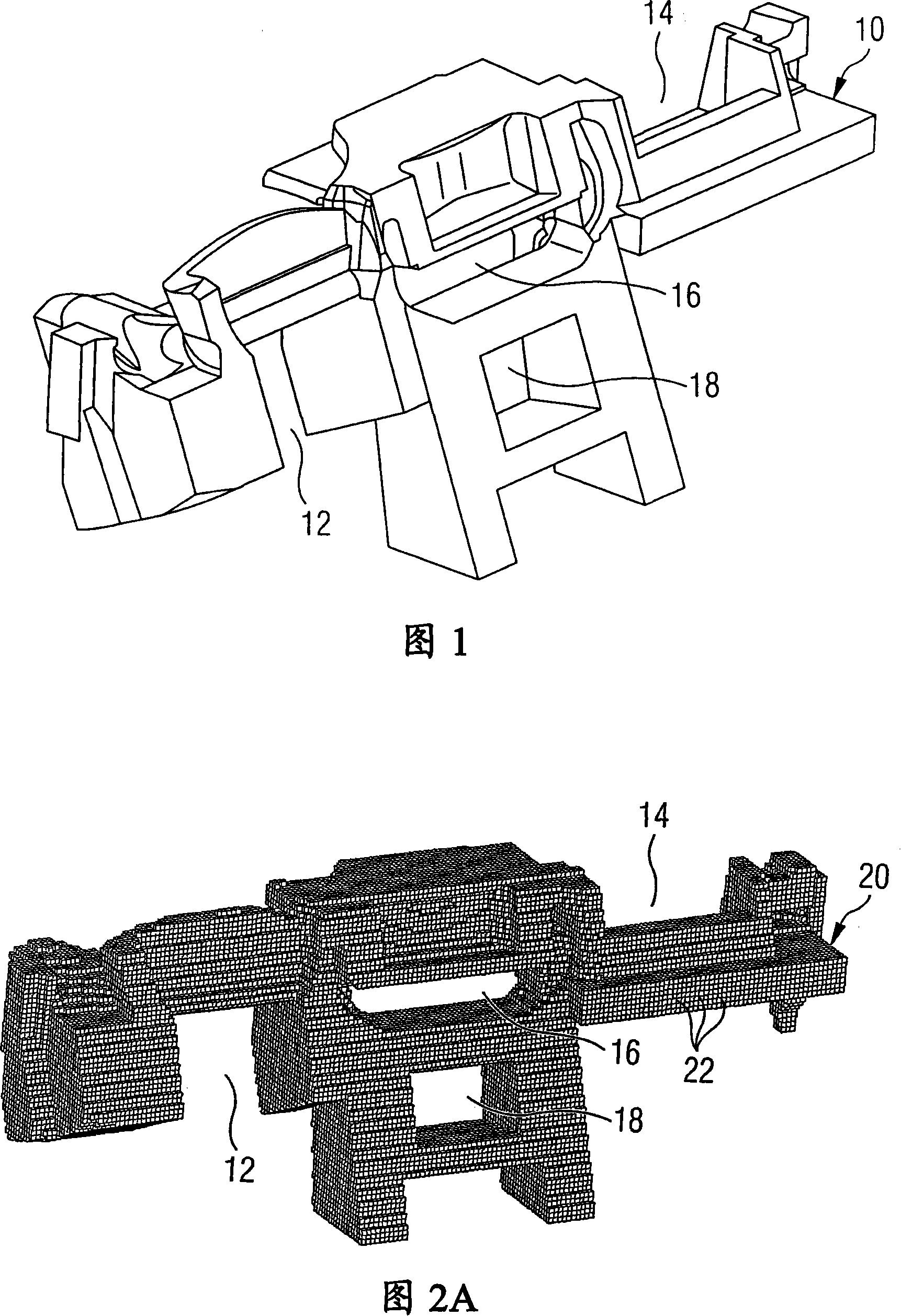
[0024] FIG. 1 shows a perspective view of an installation space 10 as it is created in the region of the cockpit of the vehicle between the bulkhead separating the engine compartment of the vehicle from the cockpit and the cockpit module. The cockpit module forms the visible surface and contains functional components of the vehicle cockpit, such as air conditioning, audio equipment, glove boxes, ashtrays, instrument brackets, etc. Furthermore, installation space remains for other vehicle components such as airbags and steering columns. A cockpit support structure is provided in the installation space 10 , which has to supportably connect the various cockpit modules to the vehicle body. Usually, such a cockpit support structure also has the meaning of supporting the vehicle body, and especially in the case of a side collision, the cockpit support structure must also withstand enormous forces and stabilize the cockpit. Since, for example, recesses 12 for the steering column, ai...


PUM


Abstract

A method for optimizing a design of a cockpit support structure (36) for motor vehicles for flexible utilization of the available installation space includes initially measuring the maximum installation space (10) available for the support structure and depicting the maximum installation space as a wire-mesh structure. The wire-mesh structure undergoes an iterative optimization process for meeting certain boundary conditions with the aim of volume and weight optimization. Finally, the wire-mesh structure obtained is realized constructively into a component which can be produced by conventional manufacturing method techniques.

Description

technical field [0001] The invention relates to a method for optimizing a cockpit support structure of a motor vehicle, which is used as a connection between vehicle body and cockpit components. Background technique [0002] Such support structures, which are installed, for example, in the form of cockpit beams in vehicles, are conventionally structurally modified and the static and dynamic load situations are subsequently checked by means of simulations and / or tests. The problem here is that, when the requirements are not met, modification or redesign may be required, especially if the defect is recognized at a very late point in the design, which greatly hinders the development process. [0003] It is also known in the automotive field to calculate and optimize support structures by means of the finite element method. In this case, the initial model based on the acquired structural experience is usually designed as a grid structure and then subjected to an iterative optim...

Claims


Application Information

Patent Timeline
Patent Type & Authority Applications(China)
IPC IPC(8): G06F17/50B62D65/00B62D25/08
CPCG06F17/5095Y02T10/82G06F17/5018G06F30/23G06F30/15
Inventor 迪尔克·蒙丁格托马斯·福尔贝格
Owner SIEMENS VDO AUTOMOTIVE AG (DE)
Why Eureka
Try Eureka