Refrigerating apparatus

A refrigeration device and refrigerant technology, applied in the direction of refrigerators, refrigeration components, refrigeration and liquefaction, etc., can solve the problems of large vibration of expanders, reliability decline, machine damage, etc., to suppress vibration, prevent machine damage, and suppress impact Effect

Inactive Publication Date: 2008-02-27
DAIKIN IND LTD
View PDF1 Cites 5 Cited by
  • Summary
  • Abstract
  • Description
  • Claims
  • Application Information

AI Technical Summary

Problems solved by technology

But, the existing problem of above-mentioned refrigerating device is, can produce very big vibration on the outlet side of expander
So on the outlet side of the expander, there is an increased chance of machine breakage due to vibration and reliability will drop significantly, which is what we fear will happen

Method used


Image

  • Refrigerating apparatus
  • Refrigerating apparatus
  • Refrigerating apparatus

Examples


Embodiment Construction

[0031] Hereinafter, embodiments of the present invention will be described in detail with reference to the drawings.

[0032] (the first embodiment of the invention)

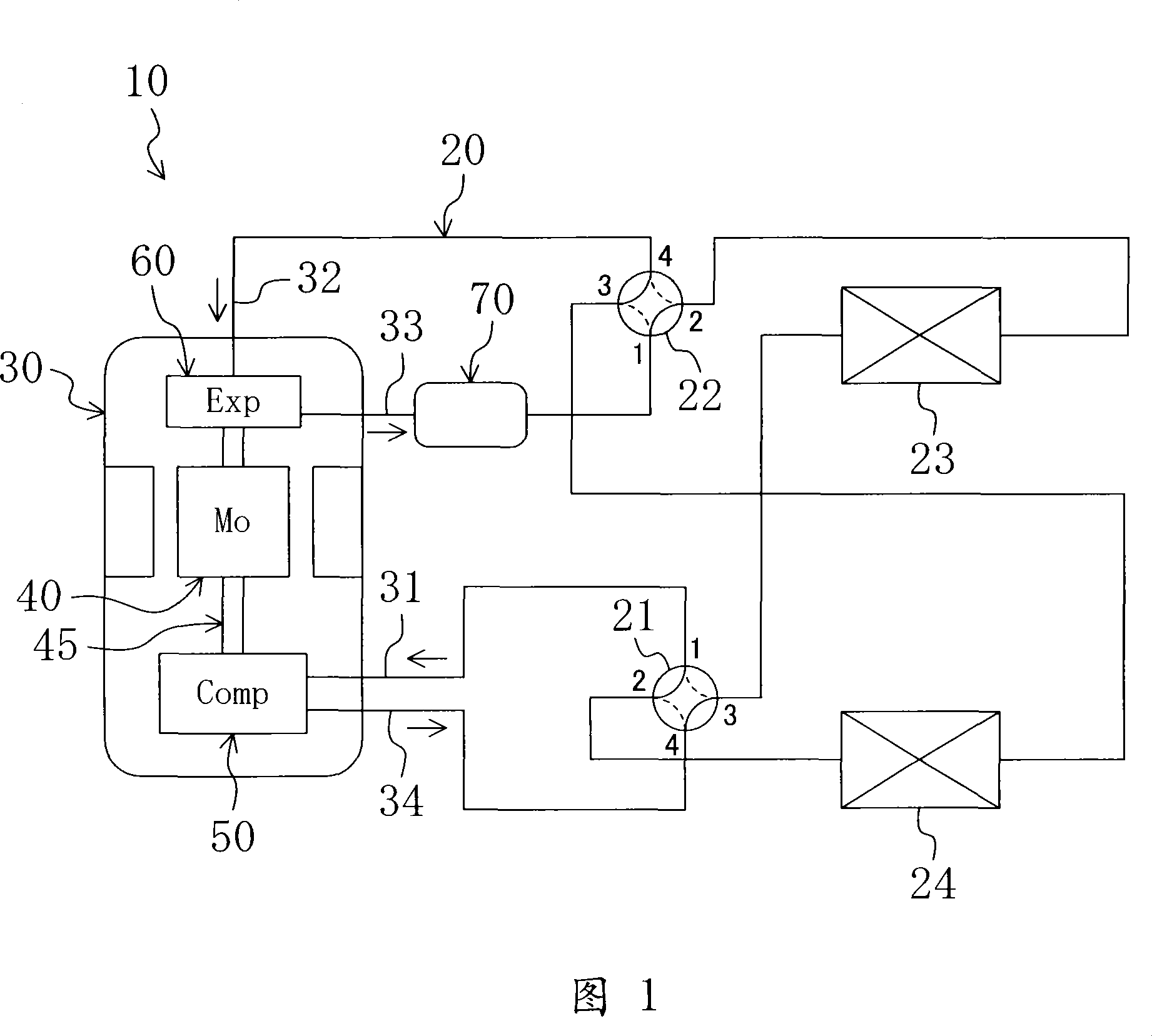
As shown in Fig. 1, the air conditioner (10) of the first embodiment is constituted as a refrigeration device according to the present invention. The air conditioner (10) includes a refrigerant circuit (20) formed as a closed circuit, and an outdoor heat exchanger (23), an indoor heat exchanger (24), two four-way reversing valves (21, 22) are connected by pipelines. ) and the compression expansion unit (30) are connected to form a closed circuit. The refrigerant circuit (20) is filled with carbon dioxide (CO 2 ), the refrigerant circulates to perform a vapor compression refrigeration cycle.

[0033] The outdoor heat exchanger (23) constitutes a heat source side heat exchanger, and the indoor heat exchanger (24) constitutes a utilization side heat exchanger. No matter which one of the outdoor heat exchanger (2...


PUM


Abstract

A buffer chamber (71) is connected to the outlet port (33) of an expansion mechanism (60). The buffer chamber (71) is formed in the shape of a cylinder extending in the direction of the flow of a cooling medium, and has a cross-sectional area greater than that of the outlet port (33). A rectifying plate (75) having a mesh section (75a) of a circular shape is provided inside the buffer chamber (71). The variation of pressure is relieved by the supply of pressure and the absorption of pressure by the buffer chamber (71), and also drops of the cooling medium are fined when they are passed through the plate (75).

Description

technical field [0001] The present invention relates to a refrigeration unit, and in particular to a measure for reducing pressure pulsations. Background technique [0002] Hitherto, refrigerating apparatuses for a vapor compression refrigerating cycle using carbon dioxide as a refrigerant are known. Such a refrigeration system includes a refrigerant circuit in which a compressor, a cooler, an expander, and an evaporator are sequentially connected (see, for example, Patent Document 1). [0003] In the refrigerant circuit of the above-mentioned Patent Document 1, the refrigerant repeats the following cycle. The refrigerant is compressed to a supercritical state by the compressor, and then cooled in the cooler. The cooled refrigerant expands and is reduced in the expander. After being compressed, it evaporates in the evaporator and returns to the compressor. This refrigerating device is used as, for example, a heating device in which a cooler is installed indoors. Patent D...

Claims


Application Information

Patent Timeline
Patent Type & Authority Applications(China)
IPC IPC(8): F25B41/06F25B11/02F25B1/00
CPCF25B2500/13F25B2313/02742F25B13/00F25B1/04F25B9/06F25B2309/061F25B2400/14F25B41/003F25B2500/01F25B41/40F25B11/02F25B11/00
Inventor 冈本昌和熊仓英二冈本哲也鉾谷克己
Owner DAIKIN IND LTD
Why Eureka
Try Eureka