
High pressure cleaning machine and operation method of the cleaning machine

A technology of high-pressure cleaners and cleaning guns, applied to cleaning methods and appliances, cleaning methods using liquids, devices using electric/magnetic methods, etc., which can solve the problems of reducing power service life, increasing manufacturing costs, and low reliability, etc. problem, to achieve the effect of reducing operation intensity, high safety, practical and reliable program

Inactive Publication Date: 2008-03-05
胡松海
View PDF0 Cites 20 Cited by
  • Summary
  • Abstract
  • Description
  • Claims
  • Application Information

AI Technical Summary

Problems solved by technology

This not only increases the manufacturing cost, but also reduces the service life of the power
At the same time, the control system of the existing high-pressure cleaner is a mechanical control system, with many components, high manufacturing cost and short service life, and the reliability of control is not high.

Method used


Image

  • High pressure cleaning machine and operation method of the cleaning machine
  • High pressure cleaning machine and operation method of the cleaning machine
  • High pressure cleaning machine and operation method of the cleaning machine

Examples


Embodiment 1

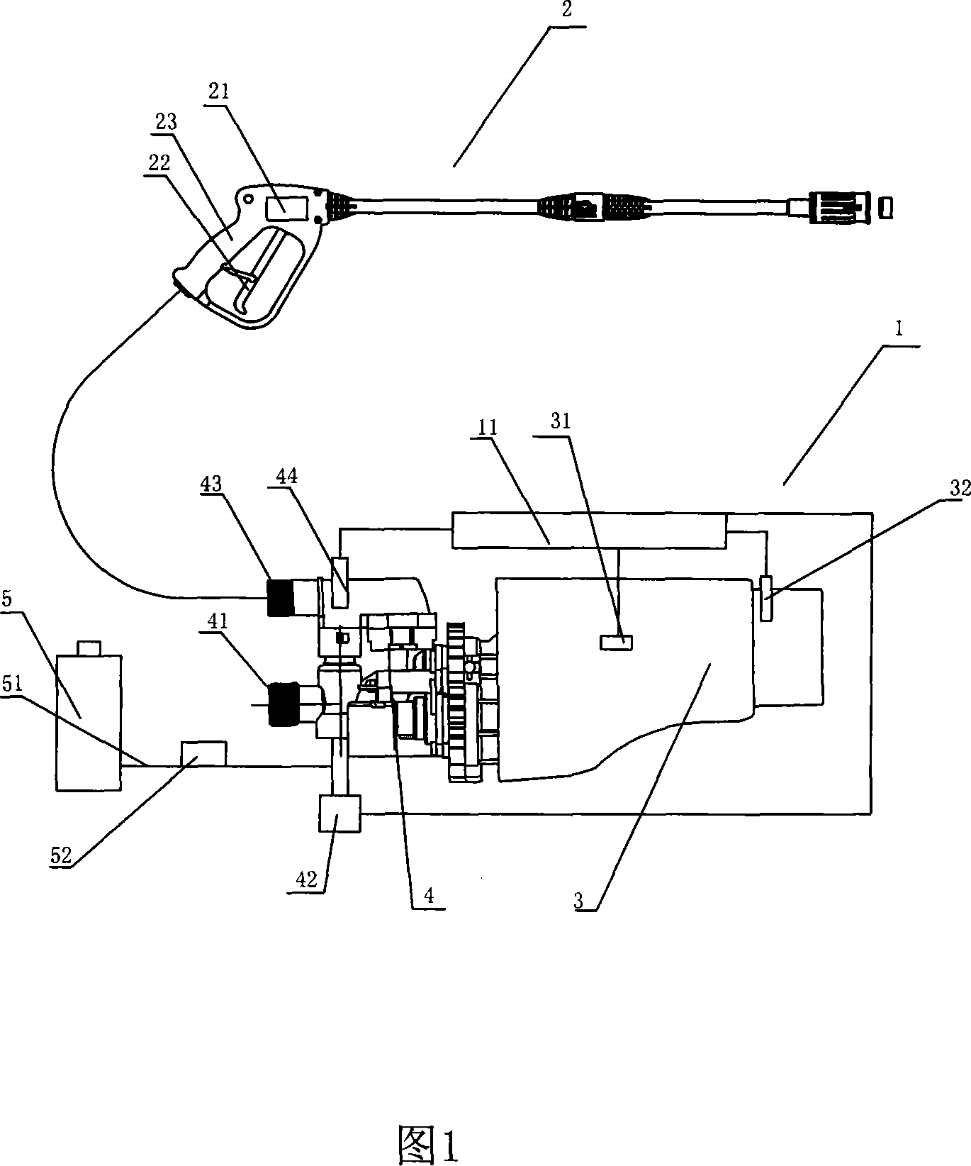
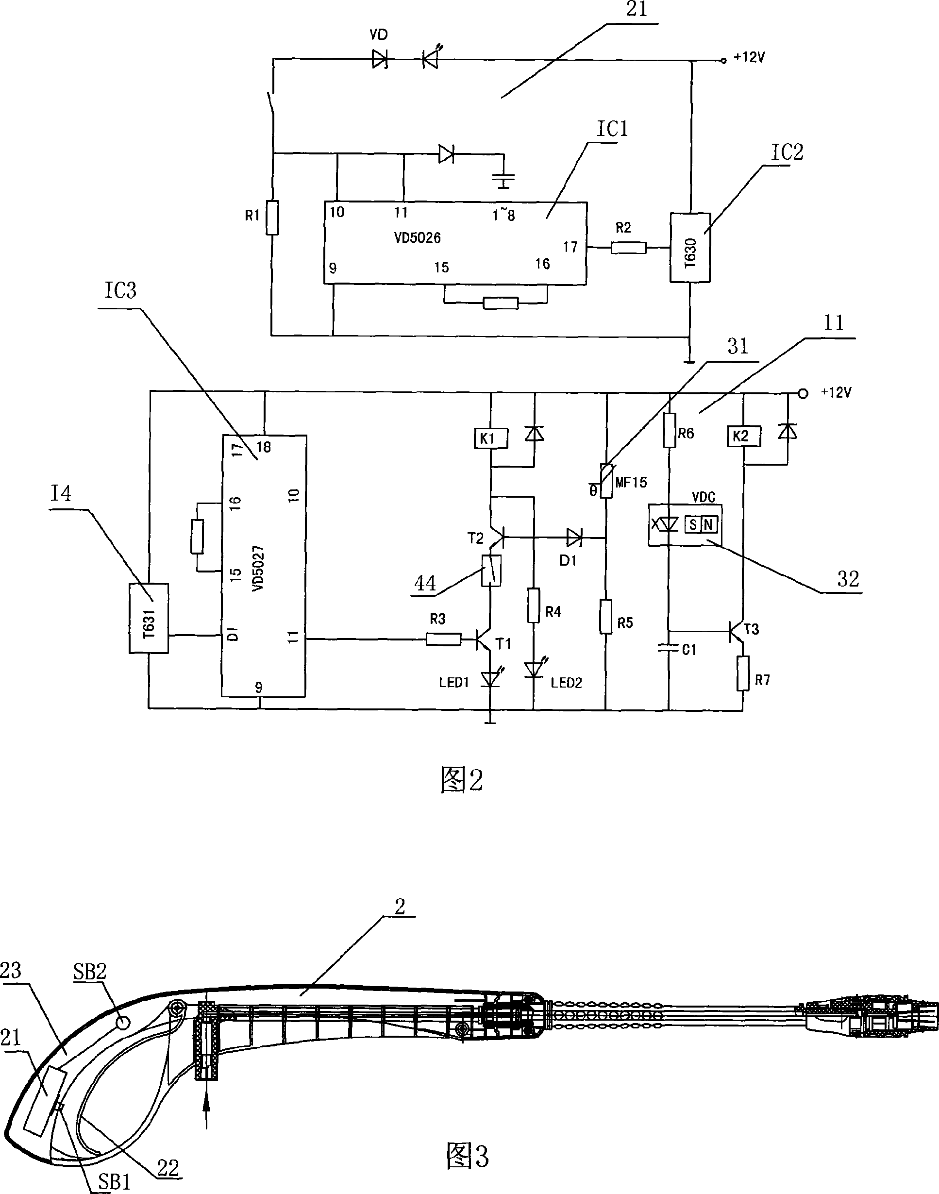
[0017] Embodiment 1: a high-pressure cleaning machine, including a host 1 and a cleaning gun 2, the host 1 includes a motor 3, a high-pressure pump 4 and a washing liquid container 5, the motor 3 is provided with a power relay switch (not shown), and the high-pressure pump 4 is provided with There is a water inlet pipe 41 connected to an external water source and an outlet pipe 42 connected to the cleaning gun 2. The washing liquid container 5 is provided with a washing liquid pipe 51 communicating with the water inlet pipe 41. The washing liquid pipe 51 is provided with a manual valve as a washing liquid switch Device 52, the cleaning gun 2 is provided with a signal transmitting device 21, the signal transmitting device 21 is provided with a first button switch SK1 corresponding to the trigger 22 of the cleaning gun 2, the host 1 is provided with a signal receiving control device 11, and the water inlet pipe 41 A water inlet solenoid valve 42 is provided, a temperature sensor ...

Embodiment 2

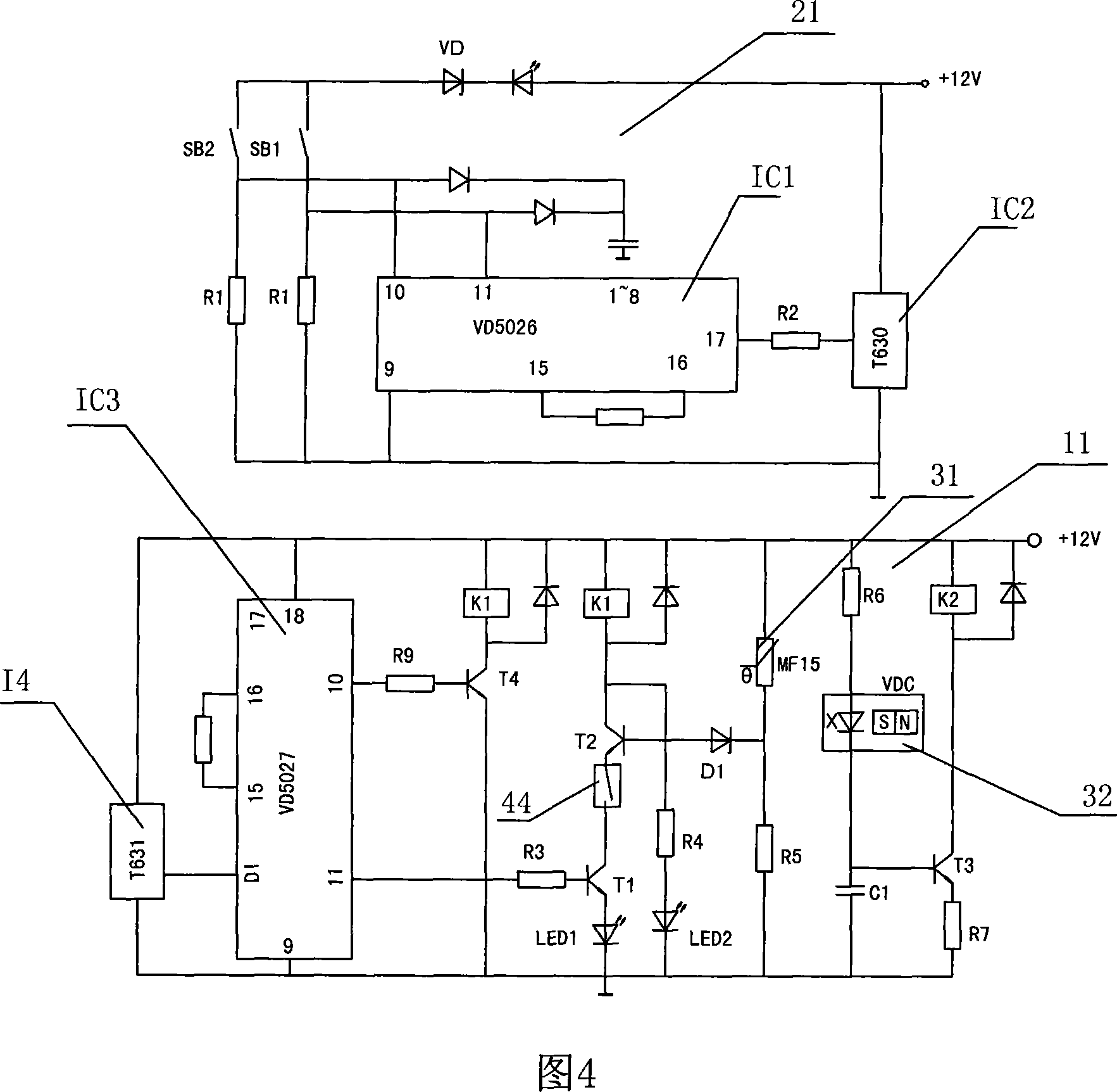
[0020]Embodiment 2: a high-pressure cleaning machine, including a host 1 and a cleaning gun 2, the host 1 includes a motor 3, a high-pressure pump 4 and a washing liquid container 5, the motor 3 is provided with a power relay switch (not shown), and the high-pressure pump 4 is provided with There is a water inlet pipe 41 connected to an external water source and an outlet pipe 42 connected to the cleaning gun 2. The washing liquid container 5 is provided with a washing liquid pipe 51 communicated with the water inlet pipe 41. The washing liquid pipe 51 is provided with a washing liquid electromagnetic valve as a cleaning solution. The liquid switch device 52, the cleaning gun 2 is provided with a signal transmitting device 21, the signal transmitting device 21 is provided with a first button switch SK1 corresponding to the trigger 22 of the cleaning gun 2, and the handle 23 of the cleaning gun 2 is provided with a second button switch SK2, the host 1 is provided with a signal r...


PUM


Abstract

The high pressure cleaning machine includes one main machine and one cleaning gun. The main machine includes one motor with one power relay switch, one high pressure pump with one water inlet pipe connected to the external water source and one water outlet pipe connected to the cleaning gun, and one detergent container with detergent pipe with switch unit and communicated to the water inlet pipe. The cleaning gun has one signal emitter with one first button corresponding to the trigger in the cleaning gun, and the main machine has corresponding signal receiving control device, water inlet solenoid valve on the water inlet pipe, temperature sensor and speed sensor on the motor, and pressure sensor on the water outlet pipe. All the sensors, the power relay switch and the water inlet solenoid valve are connected to the signal receiving control device, and the high pressure cleaning machine has the features of high safety, long service life, low cost and high reliability.

Description

technical field [0001] The invention relates to a cleaning device, in particular to a high-pressure cleaning machine and an operating method of the cleaning machine. Background technique [0002] Existing high-pressure cleaners are mainly mechanically controlled high-pressure cleaners, which require the power system to output a high torque with a large torque when starting, so that the requirements for starting the power system are very high. Manufacturers have to use special motors or start high-load internal combustion engines in order to achieve high-torque starting to meet the requirements for starting. This not only increases the manufacturing cost, but also reduces the service life of the power. At the same time, the control system of the existing high-pressure cleaning machine is a mechanical control system with many components, high manufacturing cost and short service life, and the reliability of control is not high. Contents of the invention [0003] The techni...

Claims


Application Information

Patent Timeline
Patent Type & Authority Applications(China)
IPC IPC(8): B08B3/02G08C19/00G01K7/22G01P3/42
Inventor 胡松海
Owner 胡松海
Learn More