Rolling type end face seal dissepiment

An end-face sealing, rolling technology, applied in the direction of the engine seal, diaphragm, engine components, etc., can solve the problems of not working properly, reducing the technical indicators of equipment design, and the end face diaphragm not considering the influence of axial force, etc., to achieve the scope of application Wide, improve technical indicators and production efficiency, good application effect

Inactive Publication Date: 2008-03-05
SOUTH CHINA UNIV OF TECH
View PDF0 Cites 3 Cited by
  • Summary
  • Abstract
  • Description
  • Claims
  • Application Information

AI Technical Summary

Problems solved by technology

[0002] The traditional end face diaphragm does not consider the influence of the connection between the diaphragm and the cylinder on the axial force of the moving parts (such as piston, sleeve)
In hydraulic and pneumatic equipment with precise requirements, the axial force will reduce the design technical indicators of the equipment, and even fail to work normally

Method used


Image

  • Rolling type end face seal dissepiment

Examples


Embodiment 1

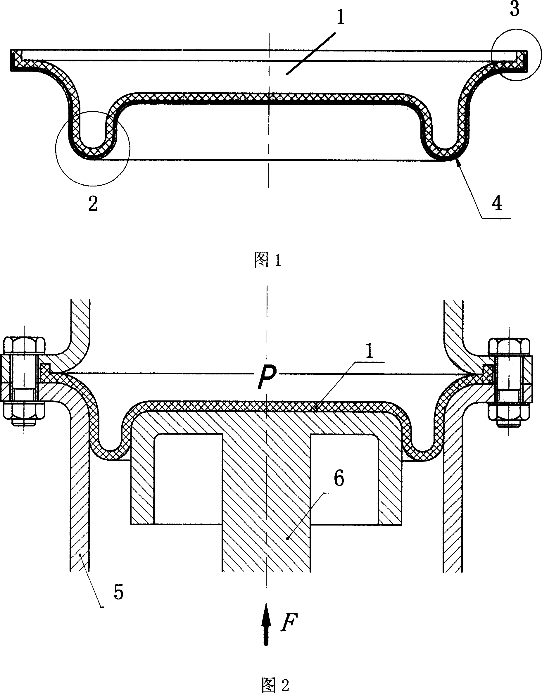
[0014] As shown in FIG. 1 , the rolling type end face sealing diaphragm 1 is in the shape of a disc, with an annular arc boss 2 on the inner surface and a flange 3 on the outer circumference. The rolling end face sealing diaphragm is made of two kinds of materials, the inner and outer layers are sealing diaphragm, and the middle layer is mesh braid 4; the sealing diaphragm is made of rubber and other materials with high elasticity, and the mesh braid is made of high strength Cotton thread, carbon fiber and other materials.

[0015] As shown in Figures 1 and 2, the rolling end face seal diaphragm works like this: the flange 3 on the outer circumference of the rolling end face seal diaphragm is installed on the cylinder body 5, which acts as a seal equivalent to the ○ ring, and the The high-pressure chamber in the cylinder body 5 is isolated from the normal pressure chamber; when the piston 6 in the cylinder body 5 moves axially within a certain range, the diaphragm at the ring-...


PUM


Abstract

This invention provides a rolling type end face sealing diaphragm, which is disc shaped. Its inner side face has ring shaped circular projection. Its outer side face has flange. This invention can ensures the moving part of hydraulic pressure, pneumatic equipment not interfere by the additional axial force generated from the connection of diaphragm and cylinder body. It works steadily. Thus, it increases technical indicators and producing efficiency. This invention can be used to general working flow.

Description

technical field [0001] The invention relates to a sealing diaphragm technology, in particular to a rolling type end face sealing diaphragm. Background technique [0002] The traditional end face diaphragm does not consider the influence of the connection between the diaphragm and the cylinder on the axial force of the moving parts (such as piston and sleeve). In hydraulic and pneumatic equipment with precise requirements, this axial force will reduce the design technical indicators of the equipment, and even fail to work normally. Contents of the invention [0003] The purpose of the present invention is to overcome the disadvantages and deficiencies of the above-mentioned prior art, and provide a rolling end face sealing diaphragm that does not generate additional axial force on moving parts. [0004] The purpose of the present invention is achieved through the following technical solutions: the rolling type end face sealing diaphragm is in the shape of a disk, with a ri...

Claims


Application Information

Patent Timeline
Patent Type & Authority Applications(China)
IPC IPC(8): F16J3/02F16J15/02
Inventor 杨凯林富春徐忠阳毋济海赵良知
Owner SOUTH CHINA UNIV OF TECH
Why Eureka
Try Eureka