Mixing delivery over-flow valve

An overflow valve, mixed transmission technology, applied in the direction of safety valve, balance valve, valve device, etc., can solve the problem that the safety valve cannot stabilize the pressure, the pressure level is limited, and there is no overflow valve, so as to achieve stable working pressure, The effect of ensuring work safety and improving production efficiency

Inactive Publication Date: 2008-03-05
SOUTH CHINA UNIV OF TECH
View PDF0 Cites 4 Cited by
  • Summary
  • Abstract
  • Description
  • Claims
  • Application Information

AI Technical Summary

Problems solved by technology

[0002] At present, there is no relief valve in the chemical industry in a substantial sense, and the traditional safety valve does not have the function of stabilizing the pressure, and there are restrictions on the pressure level. For different media viscosities, the pressure opening point is different, so the traditional safety valve cannot be used as a substitute for mixed transportation systems. overflow valve

Method used


Image

  • Mixing delivery over-flow valve
  • Mixing delivery over-flow valve

Examples


Embodiment 1

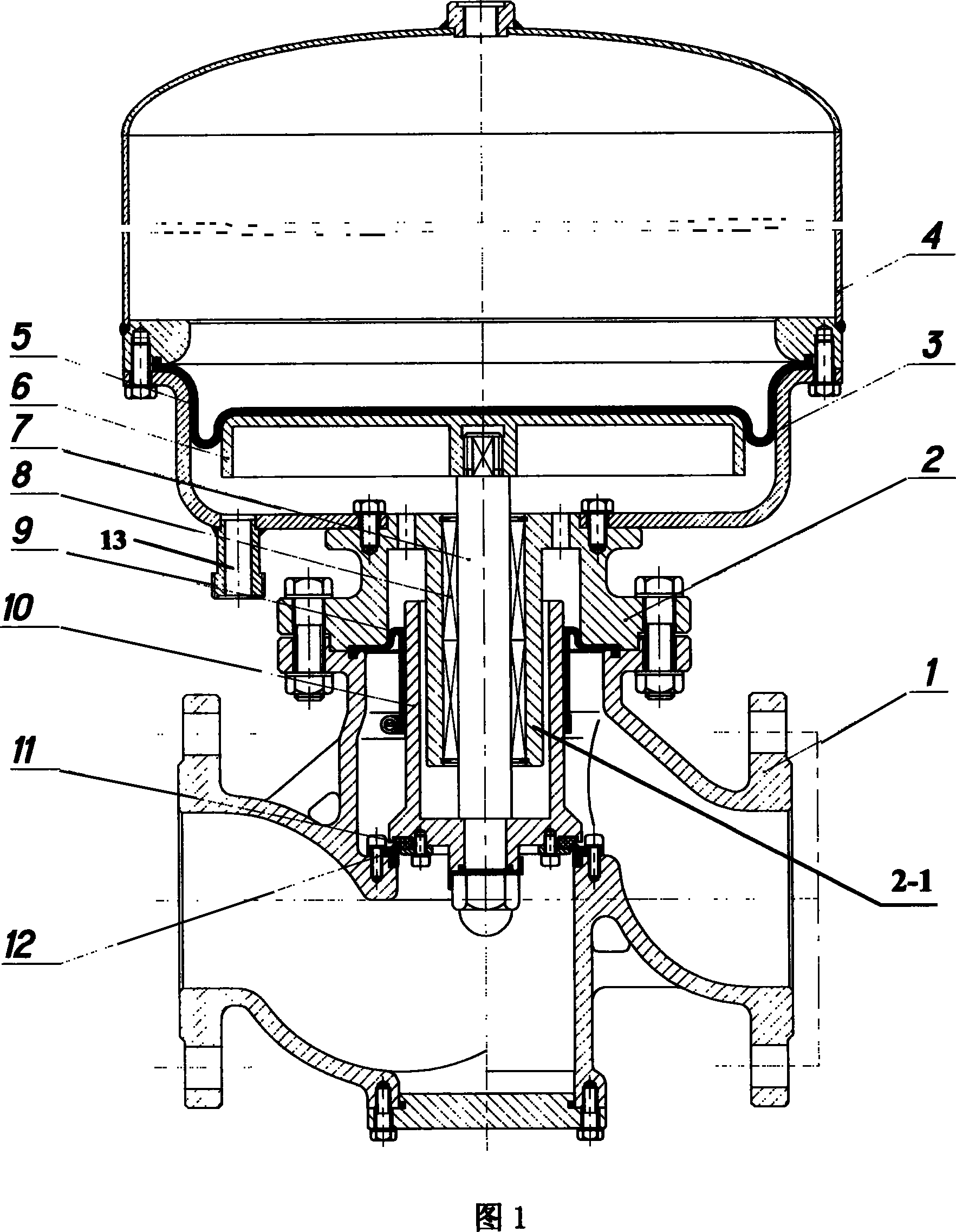
[0018] The mixed delivery relief valve includes a valve body 1, a valve seat 2, a valve core, and an air storage tank 4. The valve core includes a valve stem 7 and a valve core sleeve 10, and the lower ends of the two are fixedly connected; It is fixedly connected with the valve body 1, and the upper flange of the valve seat 2 is fixedly connected with the lower end of the gas storage tank 4 through the gas storage tank bracket 3; the middle part of the valve seat 2 is provided with a downwardly extending linear bearing sleeve 2-1, which passes through the linear bearing sleeve 2-1. The bearing 8 is socketed with the valve stem 7, the valve core sleeve 10 is socketed on the outer periphery of the bearing sleeve 2-1, the outer peripheral surface of the valve core sleeve 10 is fixedly socketed with a sealing diaphragm 9, and the upper end of the sealing diaphragm 9 is fixed around the valve body 1 and the flange end face of the valve seat 2, and between the lower end of the valve...

Embodiment 2

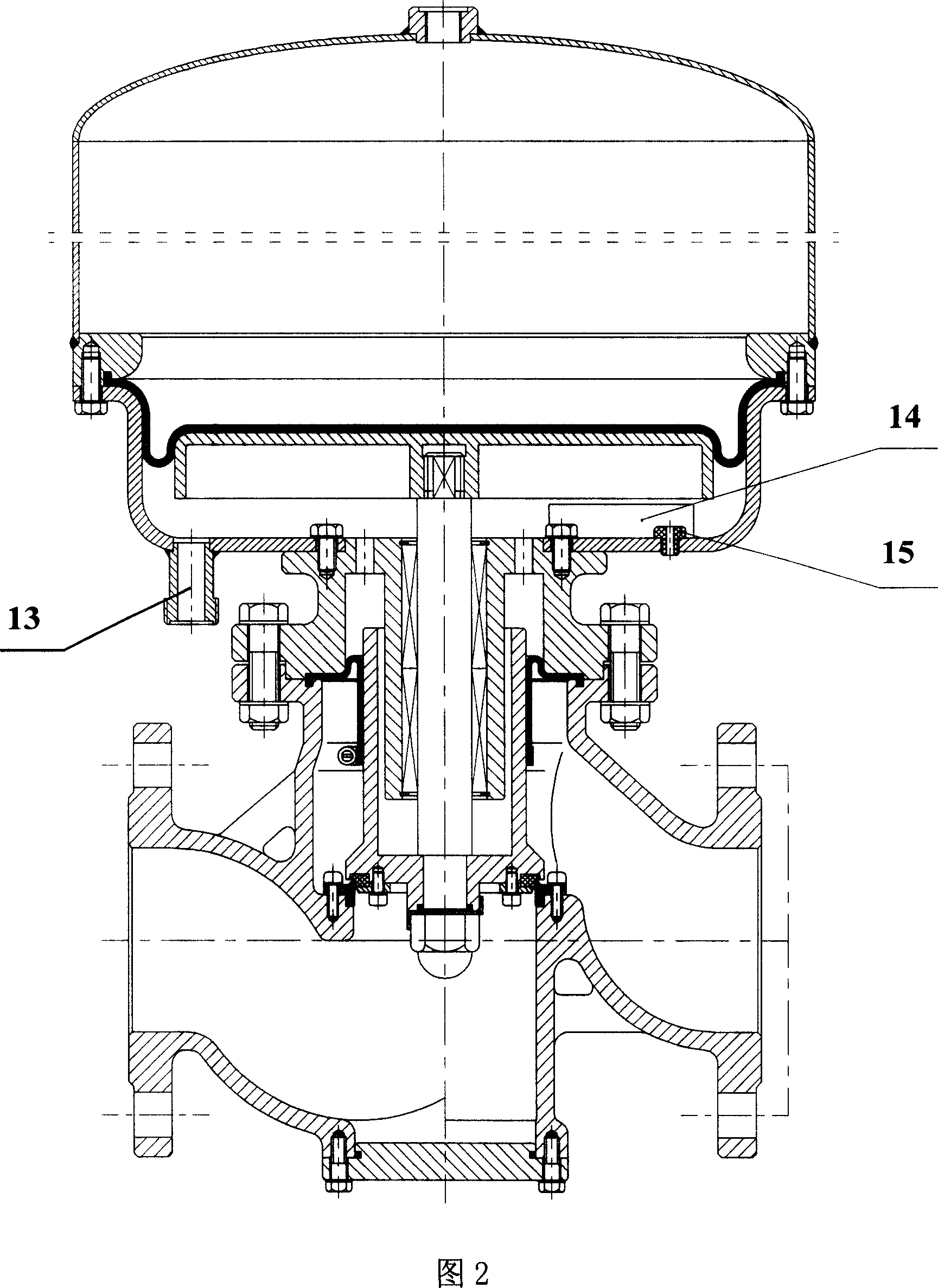
[0021] As shown in Figure 2, a sensor 14 is also provided in the air storage tank bracket 3 of the mixed transmission overflow valve, and its lead wire is connected with the remote controller through the lead wire joint 15 on the air storage tank bracket 3, and other structures are the same Example 1.

[0022] This mixed transmission overflow valve is an explosion-proof structure, suitable for highly toxic, highly corrosive, flammable, explosive or strong odor medium. Its working process is: when the system back pressure is too large and the sealing diaphragm 9 is damaged and leaks, The system is depressurized, the sensor 14 outputs an alarm signal, and the leakage medium is discharged from the emptying pipe 13 for safe treatment; other situations are the same as the common structure.


PUM


Abstract

This invention provides a mixed transportation overflow valve consisting of valve body, valve seat, valve core and gas holder. The valve core includes a valve shaft and a valve core sleeve that are fixed together at the lower parts; The lower flange of the valve seat is connected to the valve body and the upper flange is connected to the bottom of the gasholder through the gasholder bracket; a downwards extending linear bearing sleeve at the middle of the valve seat covers the valve stem by a linear bearing, the valve core sleeve is around the bearing sleeve and is surrounded by the sealing diaphragm, the upper end of the diaphragm is fixed between the valve body and the flange face of the valve seat. The upper and lower sealing pairs is set at the corresponding positions between the lower part of the valve core sleeve and the internal channel in the valve body. The gasbag is clung to the upper end of the valve stem via gasbag pallet; its upper end is fixed between the gasholder bracket and the gasholder. The drain pipe is set at the lower part of the gas holder bracket. This invention can ensure the stability of working pressure and enhance the efficiency.

Description

technical field [0001] The invention relates to a voltage stabilizing device for a mixed transportation system, in particular to a mixed transportation overflow valve. Background technique [0002] At present, there is no relief valve in the chemical industry in a substantial sense, and the traditional safety valve does not have the function of stabilizing the pressure, and there are restrictions on the pressure level. For different media viscosities, the pressure opening point is different, so the traditional safety valve cannot be used as a substitute for mixed transportation systems. relief valve. Contents of the invention [0003] The purpose of the present invention is to overcome the shortcomings and deficiencies of the above-mentioned prior art, and provide a mixed transportation overflow valve, which can ensure the stability of the working pressure of the mixed transportation system to improve production efficiency; and limit the overpressure work of the system to ...

Claims


Application Information

Patent Timeline
Patent Type & Authority Applications(China)
IPC IPC(8): F16K17/02
Inventor 杨凯林富春徐忠阳毋济海邓晓星杨卫国黄炳镇
Owner SOUTH CHINA UNIV OF TECH
Why Eureka
Try Eureka