Gilled radiator

A radiator and chip technology, applied in the field of chip radiators, can solve problems such as inability to change, inability to adjust internal excessive pressure, small space, etc., and achieve the effect of improving operational reliability.

Inactive Publication Date: 2009-04-15
SHANDONG LUSHENG ELECTRICAL EQUIP
View PDF0 Cites 3 Cited by
  • Summary
  • Abstract
  • Description
  • Claims
  • Application Information

AI Technical Summary

Problems solved by technology

[0012] The purpose of the present invention is to overcome the shortcomings of the existing fin radiators that the space is small and cannot be changed, and the internal excessive pressure cannot be adjusted, and propose a fin radiator suitable for evaporative cooling technology

Method used


Image

  • Gilled radiator
  • Gilled radiator
  • Gilled radiator

Examples


Embodiment Construction

[0034] The present invention will be further described below in conjunction with the accompanying drawings and specific embodiments.

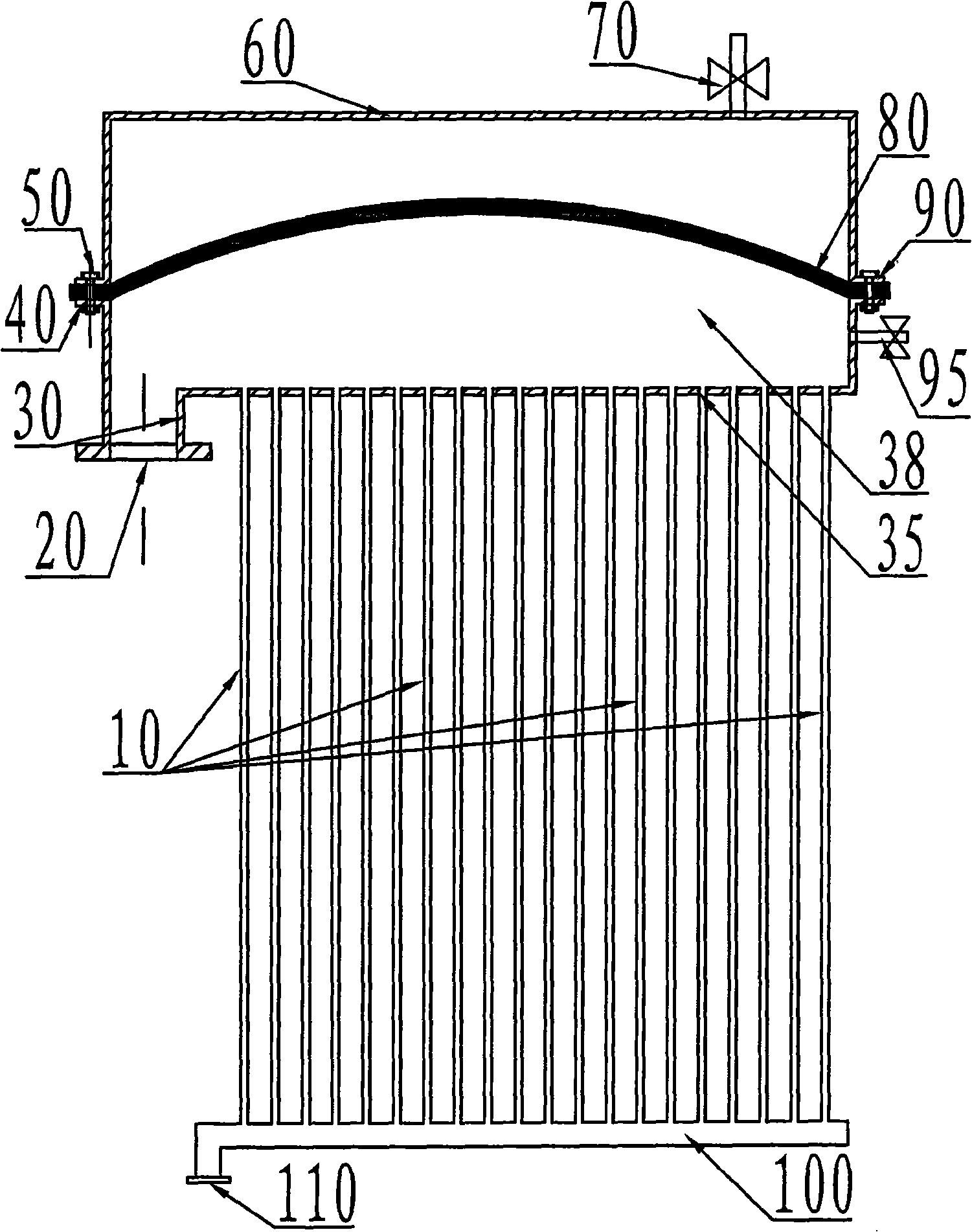
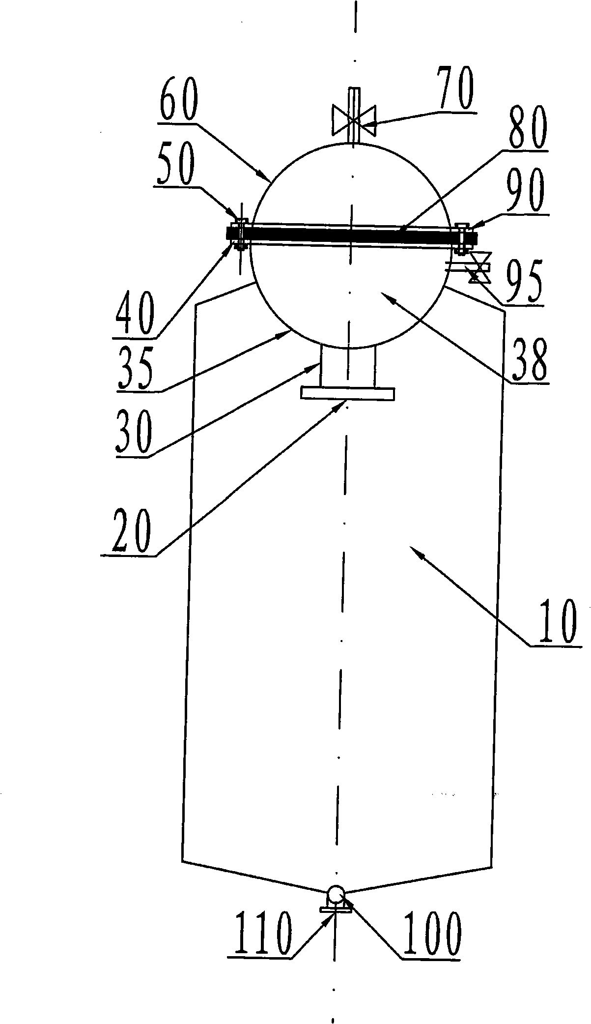
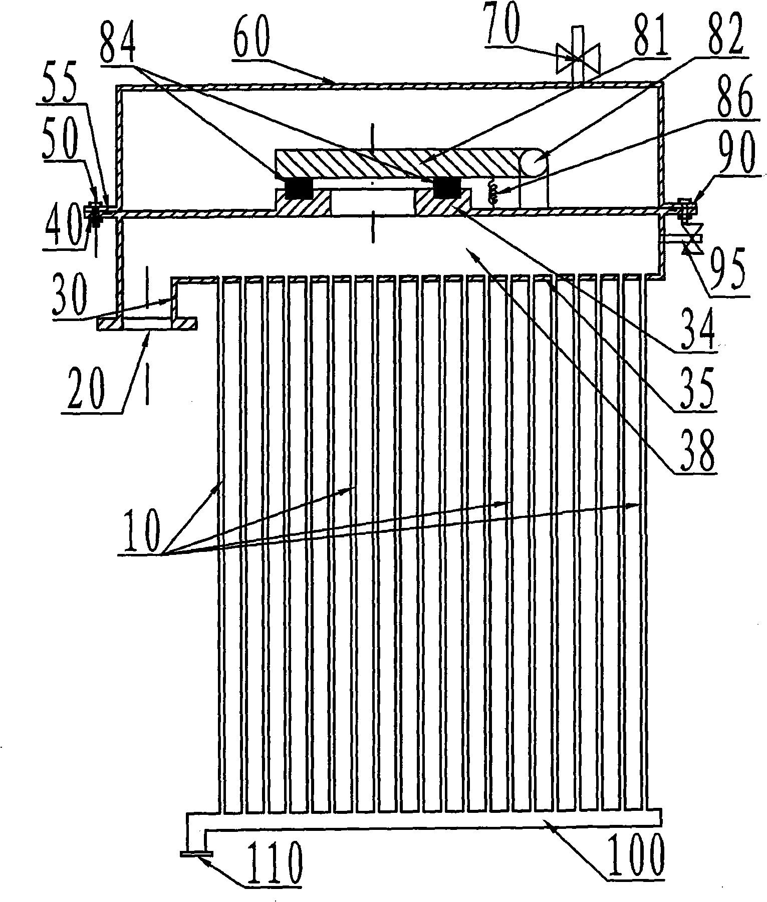
[0035] The invention includes cooling fins, air intake pipes, liquid return pipes, gas storage tanks and the like.

[0036] figure 1 and figure 2 Shown is one of the specific embodiments of the present invention. like figure 1 and figure 2 As shown, the heat sink 10 is a sealed container made of a thin metal plate with a cavity inside through welding and other processes, and can withstand a certain internal pressure. The surface of the sheet metal can have ridges or fins of various shapes. In order to reduce corrosion, the inner wall can also be painted. For a fin radiator, its radiator consists of several groups. The upper end of a group of cooling fins is connected with the gas storage tank through welding, casting and other processes, and the lower end is connected with the liquid return pipe 100 through welding, casting and other p...


PUM


Abstract

A finned radiator comprises radiating fins (10), an air inlet pipe (30), a liquid return pipe (100) and an air storage box. A diaphragm (80) or a baffle plate divides the internal space of the air storage box into upper and lower parts, and the air storage space (38) at the lower part is mutually communicated with the internal space of the radiating fins (10) and the liquid return pipe (100). Steam of a cooling medium enters the air storage space (38) through the air inlet pipe (30), then flows into each radiating fin (10) for the heat exchange with external air and turns back to liquid by condensation, and the liquid flows into the liquid return pipe (100) along the inner walls of the radiating fins (10) and flows out by a liquid return flange (110). A valve (70) at the top part of the air storage box is opened, the space above the diaphragm (80) is communicated with atmosphere, and the diaphragm (80) is correspondingly upwards convex or downwards concave along with the pressure of the steam in the air storage space (38), thereby maintaining the internal pressure of the air storage space (38) to be constant at one atmosphere pressure. The finned radiator stabilizes the internal working pressure thereof, and the cooling medium cycles naturally without the noise.

Description

technical field [0001] The invention relates to a sheet radiator for transformers, in particular to a sheet radiator dedicated to transformers using evaporative cooling technology. Background technique [0002] Traditional transformer cooling methods generally include natural oil circulation air cooling, forced oil circulation air cooling, forced oil circulation water cooling, etc. The former one is only applicable to the small capacity of a single unit. With the continuous growth of the capacity of a single transformer unit, its cooling method is increasingly dependent on the latter two, that is, using strong convective air or water as the cooling medium to run through the heat exchanger. Transformer oil in the tank for cooling. However, no matter natural oil circulation air cooling, forced oil circulation air cooling or forced oil circulation water cooling, there are inherent defects and problems. [0003] Natural oil circulation air cooling, use of chip radiator, low co...

Claims


Application Information

Patent Timeline
Patent Type & Authority Applications(China)
IPC IPC(8): H01F27/18F28F3/00
Inventor 张国强牛文豪王新
Owner SHANDONG LUSHENG ELECTRICAL EQUIP
Why Eureka
Try Eureka