
Retainer ring for CMP device, method of manufacturing the same, and CMP device

A manufacturing method and retaining ring technology, which is applied in the manufacture of tools, grinding devices, semiconductor/solid-state devices, etc., can solve the problems of not being able to adapt to the need for grinding, not being able to suppress time, and not being clear, etc., to achieve small surface roughness, The effect of reducing defective products and improving production efficiency

Inactive Publication Date: 2008-03-05
NIPPON SEIMITSU DENSHI
View PDF1 Cites 5 Cited by
  • Summary
  • Abstract
  • Description
  • Claims
  • Application Information

AI Technical Summary

Problems solved by technology

However, in the above-mentioned Patent Document 1, there is no description about the material of the retaining ring, and what kind of material of the retaining ring can make the surface roughness of the pressing surface 0.8 μm or less in terms of maximum height without needing to adapt to grinding. unclear
[0008] As described above, in the retaining ring described in the above-mentioned Patent Document 1 and its disclosure, it is of course impossible to eliminate the need for adaptive grinding, and in fact, it is impossible to suppress the time required for adaptive grinding to a minimum.

Method used


Image

  • Retainer ring for CMP device, method of manufacturing the same, and CMP device
  • Retainer ring for CMP device, method of manufacturing the same, and CMP device
  • Retainer ring for CMP device, method of manufacturing the same, and CMP device

Examples


Embodiment Construction

[0067] Hereinafter, the present invention will be described based on the illustrated embodiments.

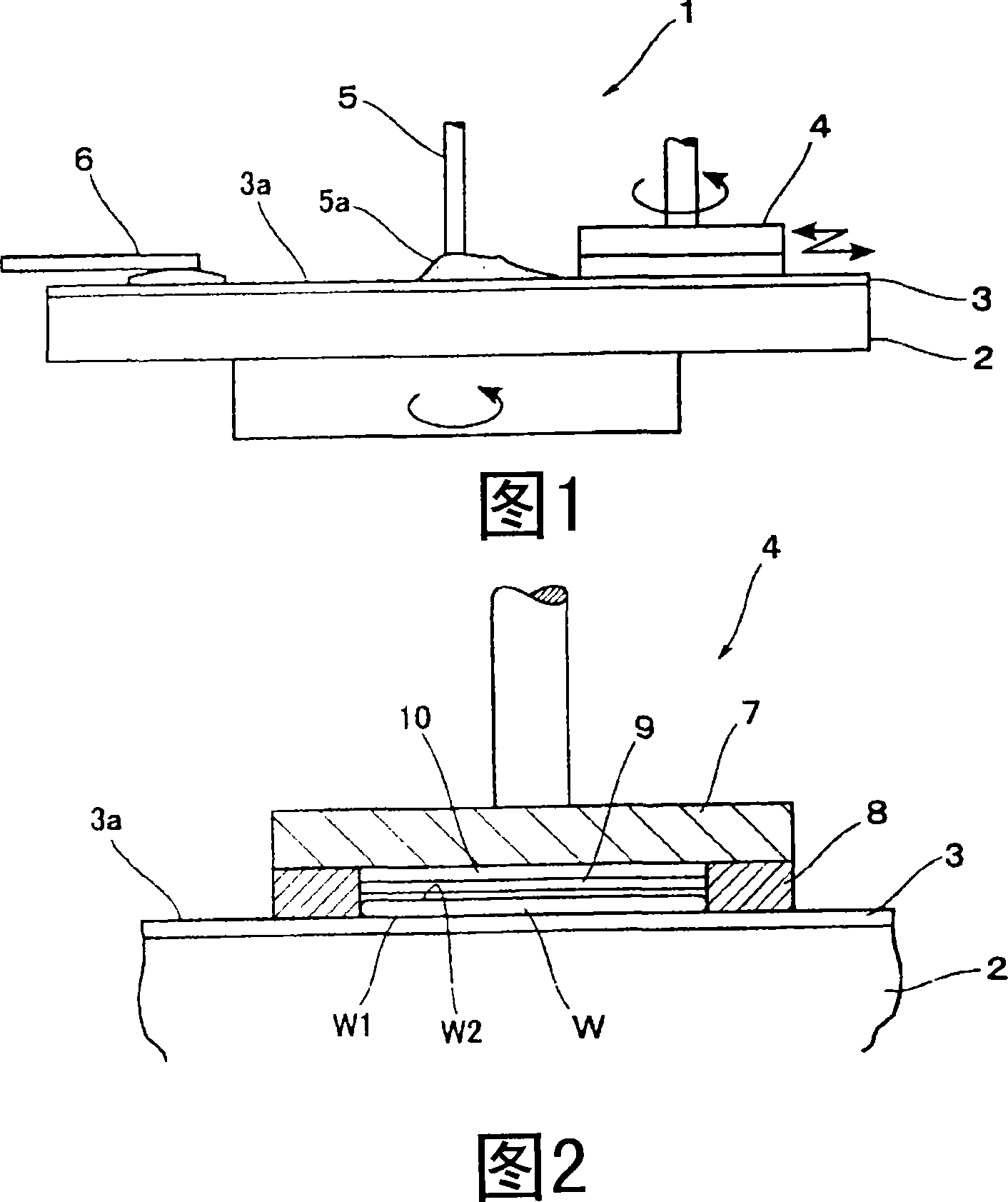
[0068] FIG. 1 is a front view showing a schematic configuration of a CMP apparatus 1 according to an embodiment of the present invention. This CMP apparatus 1 has the same structure as a widely used CMP apparatus except for a back-up ring 8 described later, and its detailed description is omitted here, but includes a rotatable grinding disc 2 and a The polishing pad 3 (fabric, etc.), the holding head 4, the slurry supply nozzle 5 (slurry supply mechanism), and the dresser 6 (shaping mechanism) are devices for performing chemical mechanical polishing W on the wafer W.

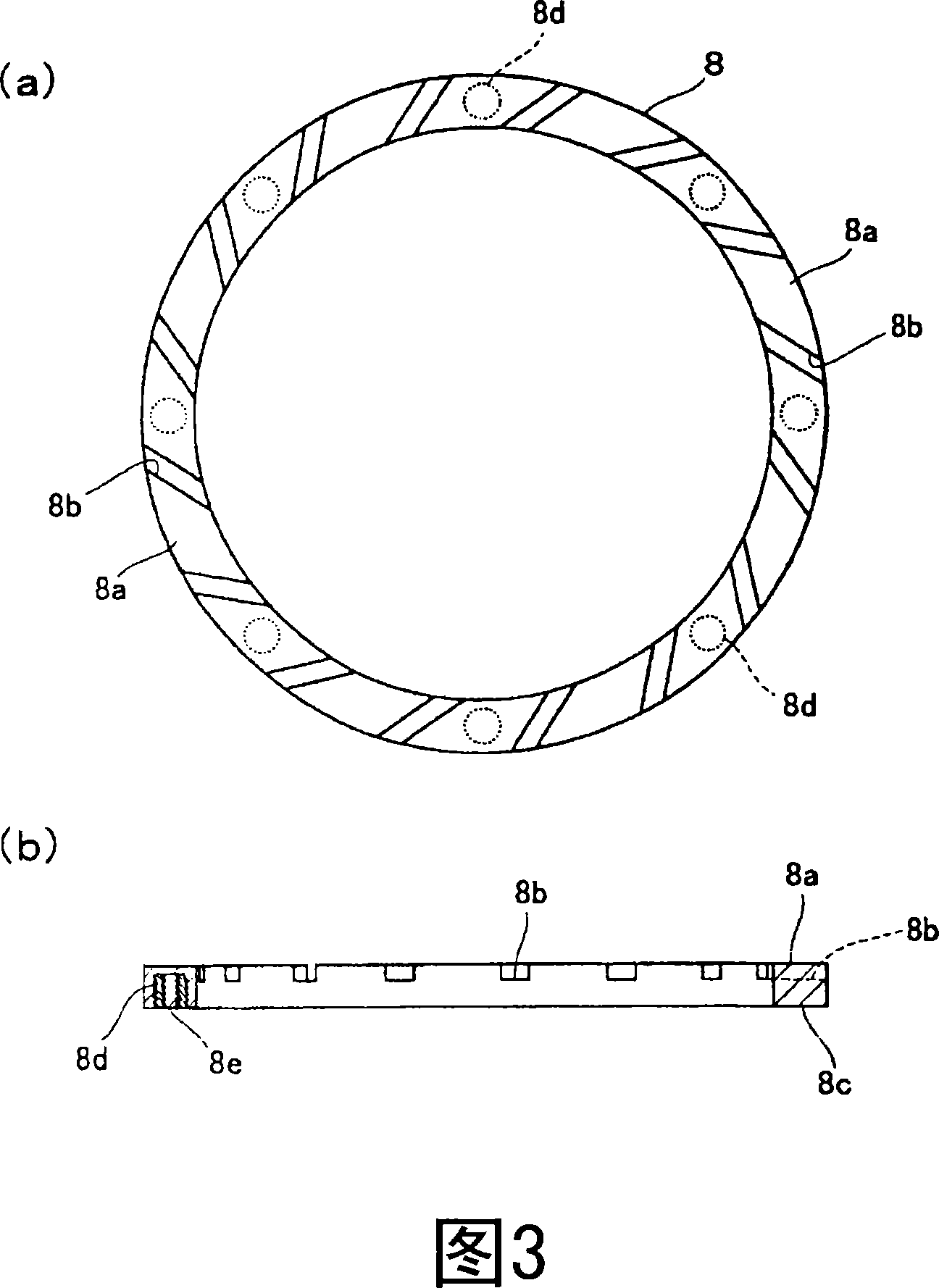
[0069] The holding head 4 holds the wafer W and presses the polished surface W1 to the polishing pad 3 , and can move on the polishing pad 3 while rotating (rotating). As shown in FIG. 2 , the holding head 4 includes a head main body 7 , a retaining ring 8 disposed under the head main body 7 , and an elastomer fi...


PUM


Abstract

A retainer ring is provided which is capable of, effectively in practice, restraining the time taken for a break-in polish to the minimum. This retainer ring 8: is disposed inside of a holding head 4 in a CMP apparatus 1 which polishes a wafer W chemically and mechanically; has a ring shape so as to surround the periphery of the wafer W; presses a polish surface 3 a of a polish pad 3; is made of an engineering plastic material such as PPS; and has a pressure surface 8 a for pressing the polish surface 3 a of the polish pad 3 whose surface roughness is a center-line average roughness (Ra) of 0.01 mum or below.

Description

technical field [0001] The present invention relates to a CMP (Chemical Mechanical Polishing) apparatus for chemically mechanically polishing a wafer, and more particularly to a retaining ring arranged (installed) in a holding head of the CMP apparatus to surround the outer periphery of the wafer. Background technique [0002] With the development of high integration and high performance of semiconductor devices, the size in the horizontal direction (on a plane) is reduced, and the structure in the vertical direction is miniaturized and multi-layered. Furthermore, in order to achieve such miniaturization and multilayering, the planarity (flatness) of the semiconductor substrate (silicon substrate, etc.) needs to be high. Therefore, improvement in flatness is required at the wafer level, and a CMP apparatus is generally used as a technology to meet such a requirement. [0003] This CMP apparatus is composed of, for example, a rotatable polishing platen, a polishing pad arran...

Claims


Application Information

Patent Timeline
Patent Type & Authority Applications(China)
IPC IPC(8): B24B37/04H01L21/304B24B37/32
CPCB24B37/32H01L21/30625B24B37/04H01L21/304
Inventor 一住连努
Owner NIPPON SEIMITSU DENSHI
Learn More