Method and system for erecting steel trusses by stay cable auxiliary complete cantilever

A technology of stay cable and steel truss girder, applied in the field of steel truss girder construction, can solve problems such as increased investment and increased load, and achieve the effects of short construction period, small investment and convenient operation

Active Publication Date: 2008-03-12
THE FOURTH ENG CO LTD OF CHINA ZHONGTIEMAJOR BRIDGE ENG GRP
View PDF0 Cites 23 Cited by
  • Summary
  • Abstract
  • Description
  • Claims
  • Application Information

AI Technical Summary

Problems solved by technology

[0005] However, as the span of the steel girder increases, the load on the temporary pier in the middle increases, especially for large-span, deep water, rapid flow, and poor geological condit...

Method used


Image

  • Method and system for erecting steel trusses by stay cable auxiliary complete cantilever
  • Method and system for erecting steel trusses by stay cable auxiliary complete cantilever

Examples


Embodiment Construction

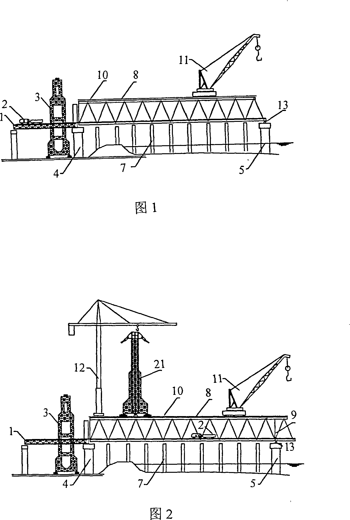
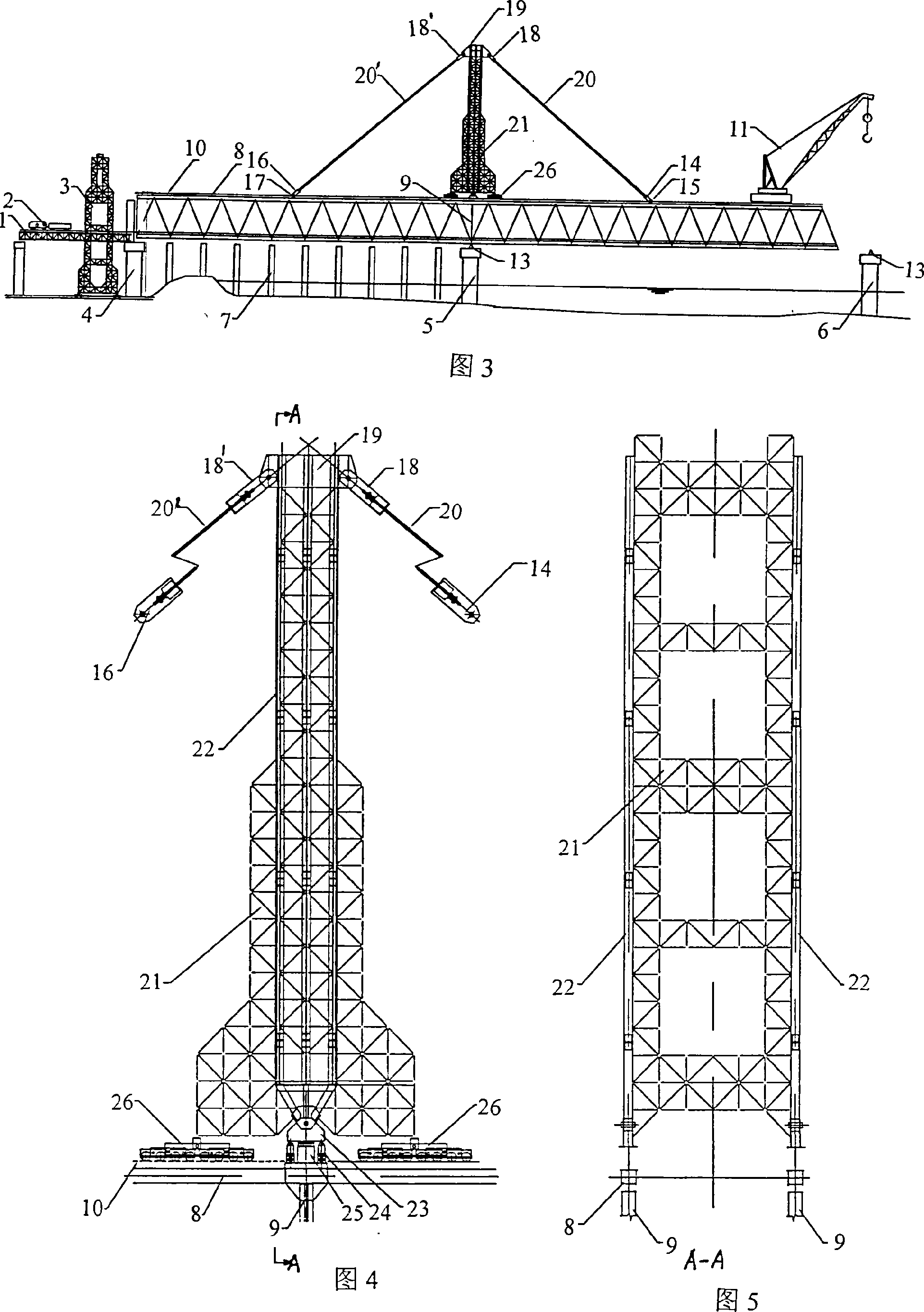
[0027] A method for erecting steel truss girders assisted by cable-stayed full cantilever, the specific steps of the method are as follows:

[0028] (1) Use a sling tower that combines a steel structure central tower column with stay cables. When applied to the erection of multi-span beams, the sling tower can be dragged and moved from one span to the next span by using the running structure installed at its lower part to erect steel truss girders. The stay cables are multi-cable group cables of one or more layers system.

[0029] (2) After the steel truss girder of the first hole is assembled on the frame, use the elevated gantry crane at the ground lifting station to install the large tower crane located on the top surface of the steel truss beam end of the first hole, and then assemble it with the tower crane Suspend the upper and lower supporting bases of the tower, the central column, the auxiliary truss and the anchor beam at the top of the tower, and then anchor the up...


PUM


Abstract

The invention is a method of erecting all-cantilever erected steel truss beams assisted by diagonal ropes, as well as a relevant system. The method utilizes a bearer cable tower combined with a steel structure center tower column with diagonal ropes; install a tower-type crane on the top face of the steel truss beam end at the first hole with an overhead bridge crane in a ground craning station; anchor cases below the front and rear diagonal ropes are connected with side plates at steel beam nodes, and after that, directly lift the tower to apply pre-tension on the diagonal ropes; perform all-cantilever erection for the front steel truss beam. After finishing erection of the orifice steel beam, complet load removal from the diagonal ropes with a method of pushing up the temporary seat for the front pier and lowering back a pushing and craning device between upper and lower seats of the bearer cable tower. The system comprises an auxiliary tower truss, a tower center vertical column, the upper and lower support seats, the front and rear diagonal ropes, the upper and lower anchor cases for diagonal ropes, a tower top anchor beam and a walking mechanism. The invention has the following advantages: For large-span continuous steel truss beams, utilize a special device additionally to erect multi-span steel truss beams, so as to reduce internal stress in installation of steel truss beam members, lower end deflection of the front extension arm, and increase the inclination stability of a steel truss beam on the extension arm. Meanwhile, the invention can low investment and short construction period and provide very convenient operation.

Description

technical field [0001] The invention relates to a method and a system for erecting steel truss girders with cable-assisted full cantilever erection for railway or highway steel truss girder bridges. It belongs to the technical field of steel truss girder erection construction. Background technique [0002] In the prior art, the construction techniques for erecting large-span continuous steel truss girders in water (or multi-span steel truss girders that are continuous first and then simply supported, the same below) mainly include the full cantilever assembly method, the front pier construction receiving bracket method, and temporary Pier semi-cantilever assembly method, stay cable assisted full cantilever assembly method. Each of these construction methods has its applicable scope and characteristics. Such as the full cantilever assembly method, this construction method is suitable for the assembly and erection of multi-span continuous steel truss beams (same as above) wi...

Claims


Application Information

Patent Timeline
IPC IPC(8): E01D21/00E01D6/00
Inventor 黄旺明刘俊查道宏卢海明欧阳平朱琪余本俊高振东袁先留黄江刚沈庆龙周祖干杨柳青陈卫成农代培潘军孙黄花吴建兴
Owner THE FOURTH ENG CO LTD OF CHINA ZHONGTIEMAJOR BRIDGE ENG GRP
Why Eureka
Try Eureka