Electromagnetic variation paddle mechanism of windmill generator
An electromechanical and magnetic steel technology, applied in the field of wind turbine electromagnetic pitch change mechanism, can solve maintenance troubles and other problems, and achieve the effects of easy maintenance, fast response, no contact friction and vibration
- Summary
- Abstract
- Description
- Claims
- Application Information
AI Technical Summary
Problems solved by technology
Method used
Image
Examples
Embodiment 1
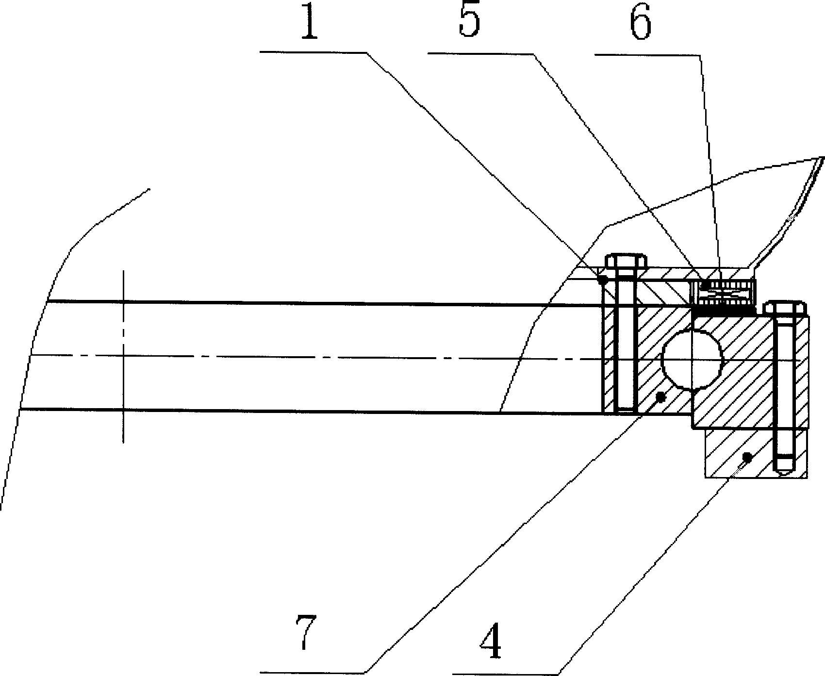
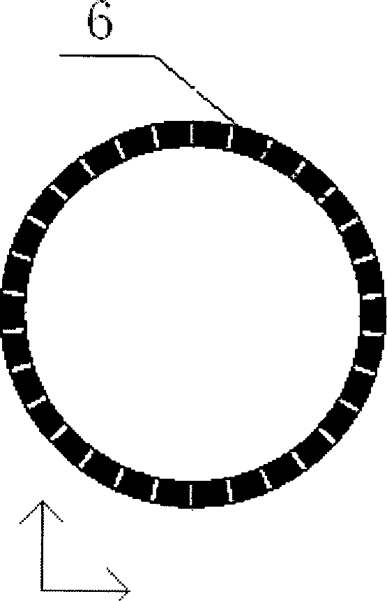
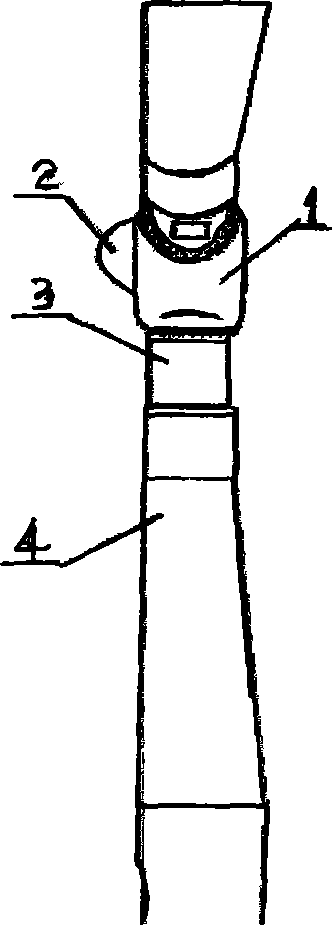
[0011] The present invention is made up of wheel hub 1, fairing 2, pitch extension joint 3, blade 4, motor winding stator 5, magnetic steel rotor 6, motor winding stator 5 and magnetic steel rotor 6 form permanent magnet stepping motor, winding The stator 5 is connected to the inner ring of the slewing support bearing 7, and the magnetic steel rotor 6 is connected to the outer ring of the slewing support bearing 7 to form a permanent magnet stepping motor support and rotation mechanism. The inner ring of the slewing support bearing 7 is connected to the blade 4 through bolts. Connected, the outer ring of the slewing support bearing 7 is connected with the hub 1 by bolts to form a pitch-changing mechanism.
[0012] Working principle: After the winding stator 2 of the motor passes a group of pulse electricity, it drives the permanent magnet stepping rotor to rotate 1 pole, and drives the blades to rotate at a certain angle to achieve the purpose of pitch change. If it is a conti...
Embodiment 2
[0014] The present invention is made up of wheel hub 1, fairing 2, pitch extension section 3, blade 4, motor winding stator 5, magnetic steel rotor 6, motor winding stator 5 and magnetic steel rotor 6 form permanent magnet stepping motor, motor winding The wire stator 5 and the magnetic steel rotor 6 form a permanent magnet stepping motor, the winding stator 5 is connected with the outer ring of the slewing support bearing 7, and the magnetic steel rotor 6 is connected with the inner ring of the slewing support bearing 7 to form a permanent magnet stepping motor support and In the rotating mechanism, the outer ring of the slewing support bearing 7 is connected to the blade 4 through bolts, and the inner ring of the slewing support bearing 7 is connected to the hub 1 through bolts to form a pitch-changing mechanism.
Embodiment 3
[0016] The present invention is made up of wheel hub 1, fairing 2, pitch extension joint 3, blade 4, motor winding stator 5, magnetic steel rotor 6, motor winding stator 5 and magnetic steel rotor 6 form permanent magnet stepping motor, winding The stator 5 is connected to the inner ring of the slewing support bearing 7, and the magnetic steel rotor 6 is connected to the outer ring of the slewing support bearing 7 to form a permanent magnet stepping motor support and rotation mechanism. The outer ring of the slewing support bearing 7 is connected to the blade 4 through bolts. Connected, the inner ring of the slewing support bearing 7 is connected with the hub 1 through bolts to form a pitch-changing mechanism.
PUM
 Abstract
Description
Claims
Application Information
 - R&D
- Intellectual Property
- Life Sciences
- Materials
- Tech Scout
- Unparalleled Data Quality
- Higher Quality Content
- 60% Fewer Hallucinations
Browse by: Latest US Patents, China's latest patents, Technical Efficacy Thesaurus, Application Domain, Technology Topic, Popular Technical Reports.
© 2025 PatSnap. All rights reserved.Legal|Privacy policy|Modern Slavery Act Transparency Statement|Sitemap|About US| Contact US: help@patsnap.com


