Platinum complex compound and organic electroluminescent device

A luminescent and electromechanical technology, applied in organic chemistry, luminescent materials, circuits, etc.

Active Publication Date: 2008-03-12
UDC IRELAND
View PDF13 Cites 68 Cited by
  • Summary
  • Abstract
  • Description
  • Claims
  • Application Information

AI Technical Summary

Problems solved by technology

However, a device capable of showing both high luminou

Method used


Image

  • Platinum complex compound and organic electroluminescent device
  • Platinum complex compound and organic electroluminescent device
  • Platinum complex compound and organic electroluminescent device

Examples


Embodiment Construction

[0051] In this specification, substituent A is defined as follows.

[0052] (Substituent A)

[0053] Illustrative alkyl groups (preferably containing 1-30 carbon atoms, more preferably 1-20 carbon atoms, especially preferably 1-10 carbon atoms; for example, methyl, ethyl, isopropyl, tert-butyl, n-octyl group, n-decyl, n-hexadecyl, cyclopropyl, cyclopentyl or cyclohexyl), alkenyl (preferably containing 2-30 carbon atoms, more preferably 2-20 carbon atoms, especially preferably 2-10 carbon atoms; for example, vinyl, allyl, 2-butenyl or 3-pentenyl), alkynyl (preferably containing 2-30 carbon atoms, more preferably 2-20 carbon atoms, especially preferably 2 - 10 carbon atoms; e.g., propargyl or 3-pentynyl), aryl (preferably containing 6-30 carbon atoms, more preferably 6-20 carbon atoms, especially preferably 6-12 carbon atoms; e.g. , phenyl, p-methylphenyl, naphthyl or anthracenyl), amino (preferably containing 0-30 carbon atoms, more preferably 0-20 carbon atoms, especially pr...


PUM


Abstract

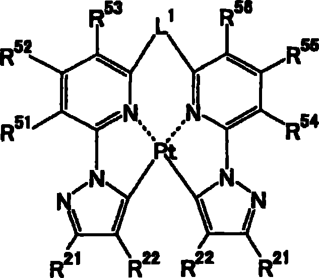
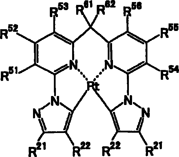
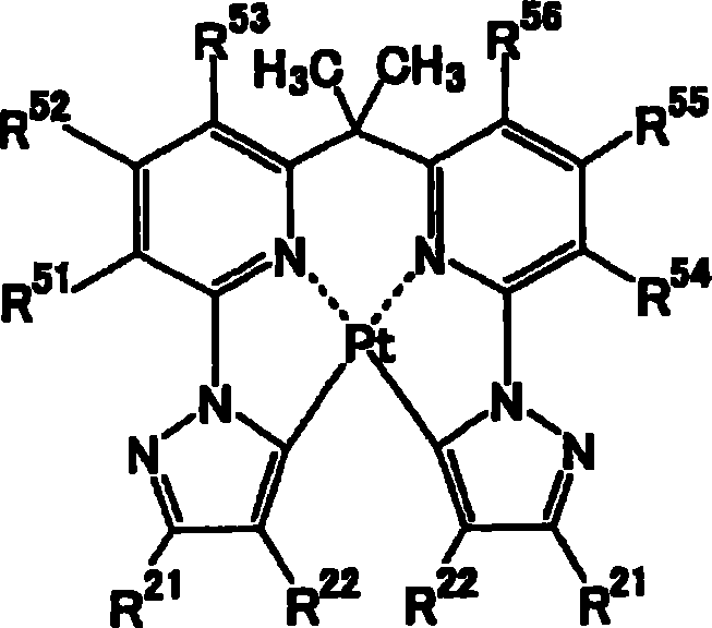
An organic electroluminescence device having at least one organic layer between a pair of electrodes is provided. The organic layer contains a compound represented by formula (I), Z1 and Z2 each represent a nitrogen-containing aromatic 6-membered ring coordinated to a platinum atom at a nitrogen atom, and Q represents a nitrogen-containing aromatic ring with one or two nitrogen atoms. In a 5-membered ring, L1 and L2 each represent a single bond or a divalent group, and n represents 0 or 1.

Description

technical field [0001] The present invention relates to a platinum complex used as a luminescent material and to an organic electroluminescent device using the same. Background technique [0002] An organic electroluminescent device can be driven at a low voltage to provide high-intensity light emission, and thus has been actively researched and developed. An organic electroluminescence device has an organic layer sandwiched between a pair of electrodes, in which electrons injected from a cathode and holes injected from an anode recombine to generate excitons, and light is emitted using the energy of the excitons. [0003] In recent years, the use of phosphorescent materials has led to improvements in the luminous efficiency of the devices. As light-emitting materials, iridium complexes or platinum complexes are known (see, for example, US Pat. No. 6,303,238 and WO 00 / 57676 pamphlet). However, an element capable of exhibiting both high luminous efficiency and high durabili...

Claims


Application Information

Patent Timeline
IPC IPC(8): C07F15/00H01L51/50C07D401/14C09K11/06
Inventor 伊势俊大五十岚达也木下郁雄邑上健
Owner UDC IRELAND
Why Eureka
Try Eureka