Vertical disc plastic injection forming machine
An injection molding machine and disc technology, applied in the field of disc-type plastic injection molding machines, can solve the problems of low production efficiency, long stroke of mold clamping cylinder piston, long time consumption, etc., so as to facilitate maintenance, improve production efficiency, shorten The effect of travel time
- Summary
- Abstract
- Description
- Claims
- Application Information
AI Technical Summary
Problems solved by technology
Method used
Image
Examples
Embodiment 1
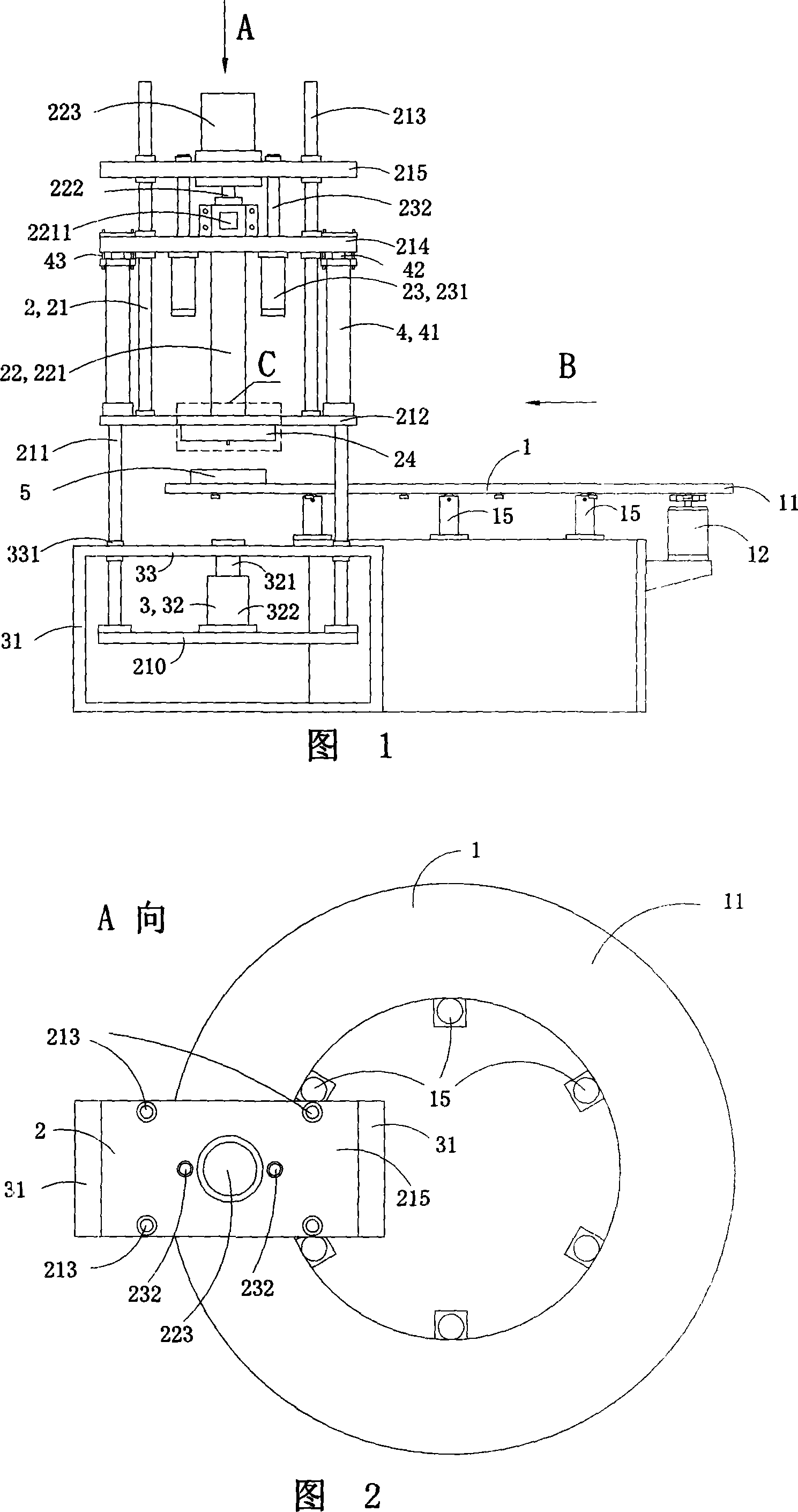
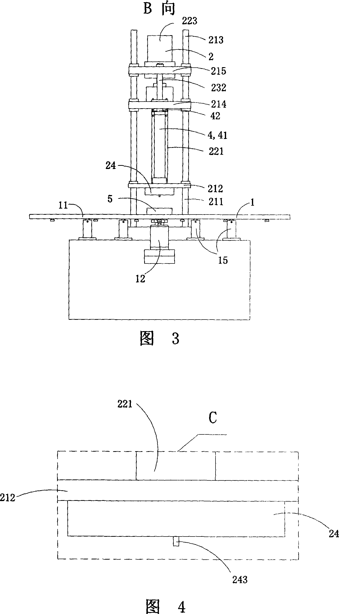
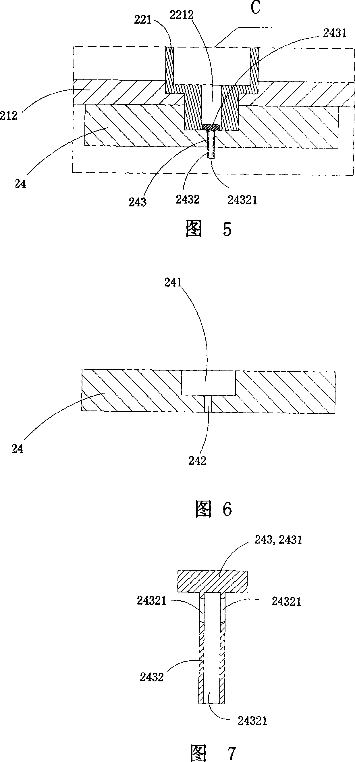
[0040] 1 to 7 show a first embodiment of the present invention. Wherein, Fig. 1 is a schematic view of the first structure of the present invention; Fig. 2 is a view to A of Fig. 1; Fig. 3 is a view to B of Fig. 1; Fig. 4 is a partially enlarged schematic view at C in Fig. 1; Fig. 5 is a view of Fig. 4; Figure 6 is a schematic structural view of the injection head in Figure 1; Figure 7 is a schematic structural view of the injection nozzle in Figure 1.
[0041] See Fig. 1 to Fig. 3, this embodiment is a kind of monochromatic vertical disc plastic injection molding machine, comprises turntable device 1, injection device 2 and clamping device 3; Said turntable device 1 comprises rotatable disc 11, A fixed stand 15 for lifting the disc 11 and a drive device 12 for driving the disc 11 to rotate, the drive device 12 can be driven by an electric motor or a hydraulic motor; the injection device 2 Including injection frame 21 and vertical pre-molding mechanism 22, injection cylinder ...
Embodiment 2
[0057] 8 to 10 show a second embodiment of the present invention. Among them, Fig. 8 is a schematic diagram of the second structure of the present invention; Fig. 9 is a view taken along the direction D of Fig. 8; Fig. 10 is a schematic diagram of the structure of the injection nozzle in the vertical disc plastic injection molding machine shown in Fig. 8 .
[0058] This embodiment is basically the same as Embodiment 1, the difference is: see Fig. 8 to Fig. 9, the vertical disc plastic injection molding machine of this embodiment is no longer equipped with a spare oil cylinder, but the injection plate 214 is fixedly arranged In the middle of the column 213.
[0059]See Fig. 10, in addition, the discharge channel 24321 in the injection nozzle in this embodiment is a groove arranged on the outer surface of the discharge part 2432 along the vertical direction.
[0060] The working process of this embodiment is the same as that of Embodiment 1, except that when maintaining and cle...
Embodiment 3
[0062] Figure 11 shows a third embodiment of the present invention.
[0063] This embodiment is basically the same as Embodiment 1, the difference is that, as shown in Figure 11, the turntable device 12 also has a fixed position relative to the mold clamping frame 31 during injection molding, that is, when the injection head is pressed against the mold. The pressure-bearing tray 13 for supporting the disc 11 is used to lift the disc 11 and be higher than the pressure-bearing tray 13 during non-injection molding, that is, when the injection head is no longer pressed against the mold. There are two elastic standoffs 14 and four rigid fixed standoffs 15 on the upper surface of the tray 13 .
[0064] In the vertical disc plastic injection molding machine of this embodiment, when the disc 11 is not pressed downward by the injection head 24, the elastic standoff 14 lifts the disc 11 up and out of the The upper surface of the pressure-bearing tray 13 is 2 mm to 5 mm, so that the rot...
PUM
 Abstract
Description
Claims
Application Information
 - R&D
- Intellectual Property
- Life Sciences
- Materials
- Tech Scout
- Unparalleled Data Quality
- Higher Quality Content
- 60% Fewer Hallucinations
Browse by: Latest US Patents, China's latest patents, Technical Efficacy Thesaurus, Application Domain, Technology Topic, Popular Technical Reports.
© 2025 PatSnap. All rights reserved.Legal|Privacy policy|Modern Slavery Act Transparency Statement|Sitemap|About US| Contact US: help@patsnap.com


