
Electric vehicle driving device with speed variator and flexible combination

A technology of flexible combination and driving device, which is applied in the field of electric vehicles, can solve problems such as difficult to meet, and achieve the effects of simple processing, low cost and convenient installation

Inactive Publication Date: 2008-03-19
广州天马集团天马摩托车有限公司
View PDF0 Cites 20 Cited by
  • Summary
  • Abstract
  • Description
  • Claims
  • Application Information

AI Technical Summary

Problems solved by technology

[0002] The driving device of the existing electric vehicle is a single motor, including a stator and a rotor. A silicon steel sheet and a permanent magnet are installed on the stator or rotor, and a winding coil is arranged on the silicon steel sheet. After being energized, an electromagnetic field is generated, and the interaction between the magnetic field and the magnetic field It is difficult for this kind of electric vehicle motor to meet the needs of starting and climbing; some electric vehicle motors are equipped with deceleration mechanisms to meet the needs of starting and climbing, but they still cannot meet the needs of the market and The customer proposed that the electric vehicle should not only meet the needs of starting and climbing, but also be able to stop on the slope and start the demand

Method used


Image

  • Electric vehicle driving device with speed variator and flexible combination
  • Electric vehicle driving device with speed variator and flexible combination
  • Electric vehicle driving device with speed variator and flexible combination

Examples


Embodiment Construction

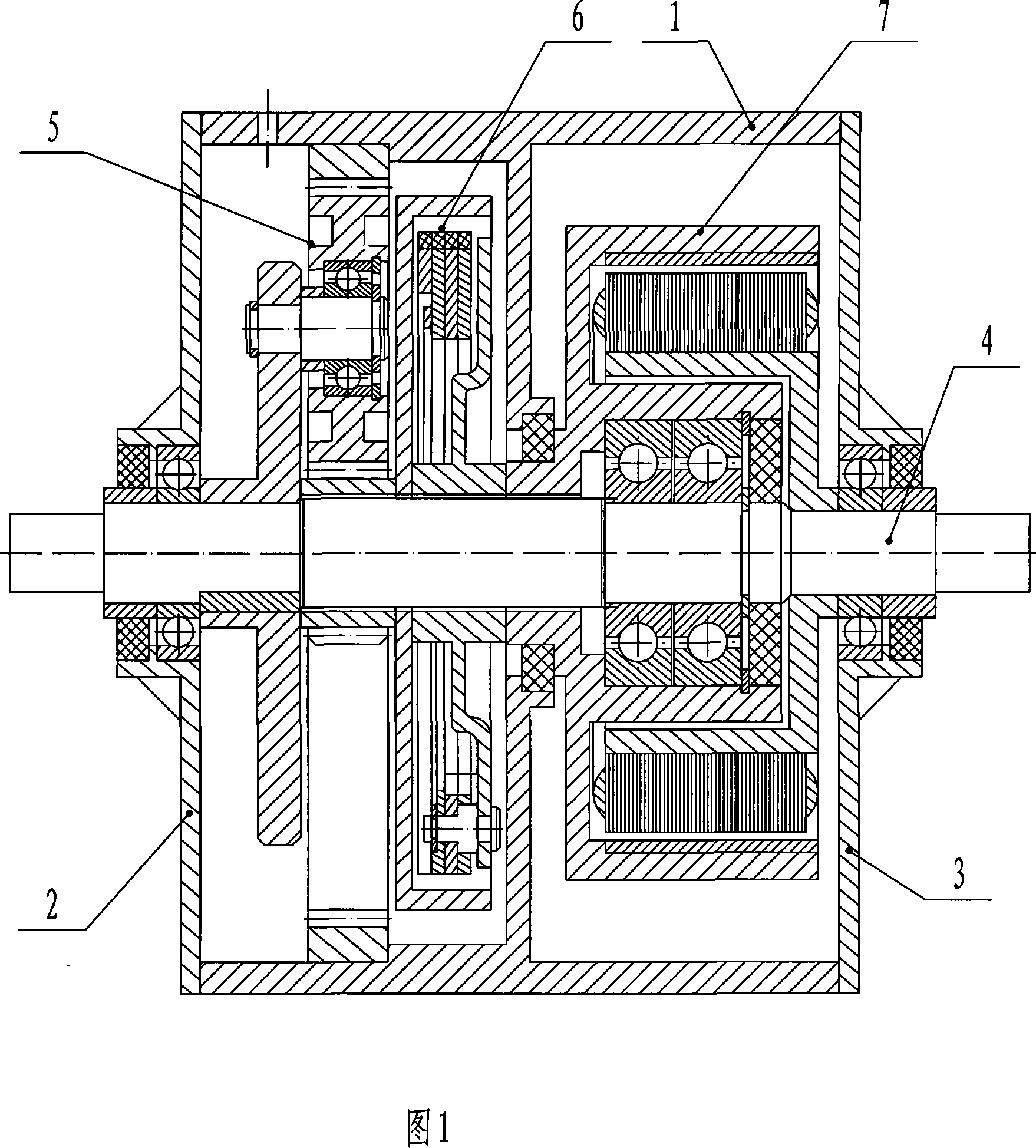
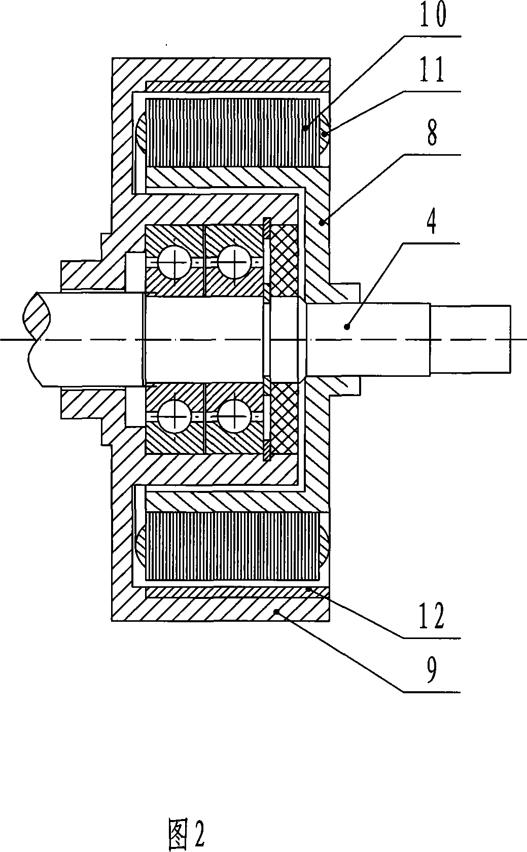
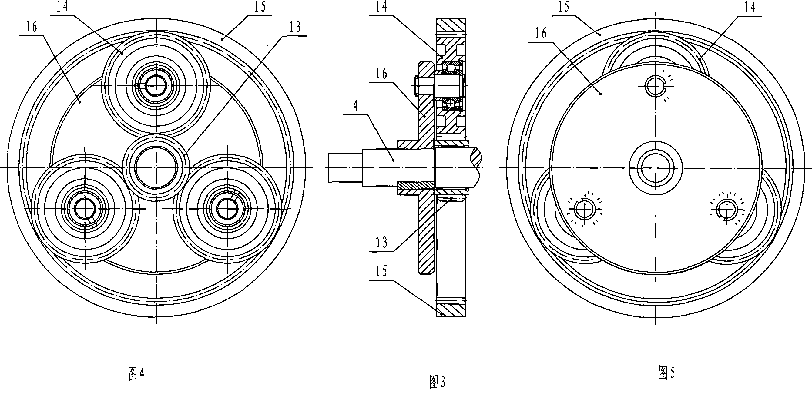
[0018] A specific embodiment is described as follows in conjunction with Fig. 1, Fig. 2, Fig. 3, Fig. 4, Fig. 5, Fig. 6 and Fig. 7: an electric vehicle driving device with a transmission and a flexible combination with a transmission and a centrifugal clutch, including a wheel hub, a left Cover plate, right cover plate, center shaft, motor, transmission and centrifugal clutch. The motor adopts an external rotor high-speed motor. The stator is fixed between the right section of the central shaft and the inner wall of the rotor. There is a silicon steel sheet on the stator, and a winding coil on the silicon steel sheet, which is connected to the electronic controller. The rotor is mounted on the Between the right section of the inner wall of the hub and the right section of the central shaft, its right end is connected with the star wheel of the overrunning clutch; it can rotate around the central shaft, and there is a permanent magnet on the inner wall of the rotor. The centrif...


PUM


Abstract

A drive device of motor vehicle with gear box and flexible combination belongs to the technical field of motor vehicles. The technical problem to be solved is to provide a drive device with gear box and centrifugal clutch. The technical proposal is as follows: the drive device of motor vehicle with gear box and flexible combination includes a wheel hub, a left cover plate, a right cover plate, a central shaft, a motor, a gear box and a centrifugal clutch; the wheel hub is provided with a left and a right sections; the central shaft is arranged in the wheel hub; the motor is arranged between the right section of the central shaft and the inner wall of the right section of the wheel hub; the left and the right cover plates are respectively arranged on both ends of the central shaft and fixed on the two end faces of the wheel hub; the gear box is arranged between the left section of the central shaft and the left end on the inner wall of the left section of the wheel hub, the input of which is connected with the centrifugal clutch and the output is connected with the wheel hub; the centrifugal clutch is arranged between the left section of the central shaft and the right end of the inner wall of the left section of the wheel hub, the input of which is connected with the motor and the output is connected with the gear box. The invention has the advantages that the drive device of motor vehicle meet the requirements for the motor vehicle to start up, climb slope and start on the slope; when running, the motor vehicle can slide with the power turned off, so as to save power.

Description

technical field [0001] It belongs to the technical field of electric vehicles. Background technique [0002] The driving device of the existing electric vehicle is a single motor, including a stator and a rotor. A silicon steel sheet and a permanent magnet are installed on the stator or rotor, and a winding coil is arranged on the silicon steel sheet. After being energized, an electromagnetic field is generated, and the interaction between the magnetic field and the magnetic field It is difficult for this kind of electric vehicle motor to meet the needs of starting and climbing; some electric vehicle motors are equipped with deceleration mechanisms to meet the needs of starting and climbing, but they still cannot meet the needs of the market and The customer proposed that the electric vehicle not only needs to meet the needs of starting and climbing, but also needs to be able to start when parked on a slope. Contents of the invention [0003] The technical problem to be s...

Claims


Application Information

Patent Timeline
IPC IPC(8): B60K17/06B60K17/02B60B27/04H02K21/12H02K29/00H02K1/27H02K1/12F16H3/44F16D43/02
Inventor 刘维嘉
Owner 广州天马集团天马摩托车有限公司
Learn More