
Electric driving system for electric vehicle and control method of electric driving system

An electric drive system, electric vehicle technology, applied in electric vehicles, DC motor speed/torque control, control drive and other directions, can solve problems such as high cost, large volume, single-motor system cannot guarantee reliability and requires fault-tolerant operation capability. , to achieve the effect of large starting torque and wide speed regulation range

Active Publication Date: 2012-02-22
SOUTHEAST UNIV
View PDF5 Cites 4 Cited by
  • Summary
  • Abstract
  • Description
  • Claims
  • Application Information

AI Technical Summary

Problems solved by technology

The single-motor system cannot well solve the contradiction between the torque-speed characteristics of the motor and the power demand of the vehicle, and its control method is also single
If the power is constant, the requirements of acceleration performance and maximum vehicle speed cannot be met; if the power performance of the vehicle is pursued, the power of the motor must be increased to increase the volume of the motor and the mass of the vehicle
More importantly, the single-motor system cannot guarantee reliability requirements and strong fault-tolerant operation capabilities
The use of a multi-motor combination structure leads to a complex structure, large volume, and high cost of the electric drive system of the vehicle, and the control method of the electric drive system is also very complicated.

Method used


Image

  • Electric driving system for electric vehicle and control method of electric driving system
  • Electric driving system for electric vehicle and control method of electric driving system
  • Electric driving system for electric vehicle and control method of electric driving system

Examples


Embodiment Construction

[0021] The present invention will be further explained below in conjunction with the accompanying drawings and specific embodiments.

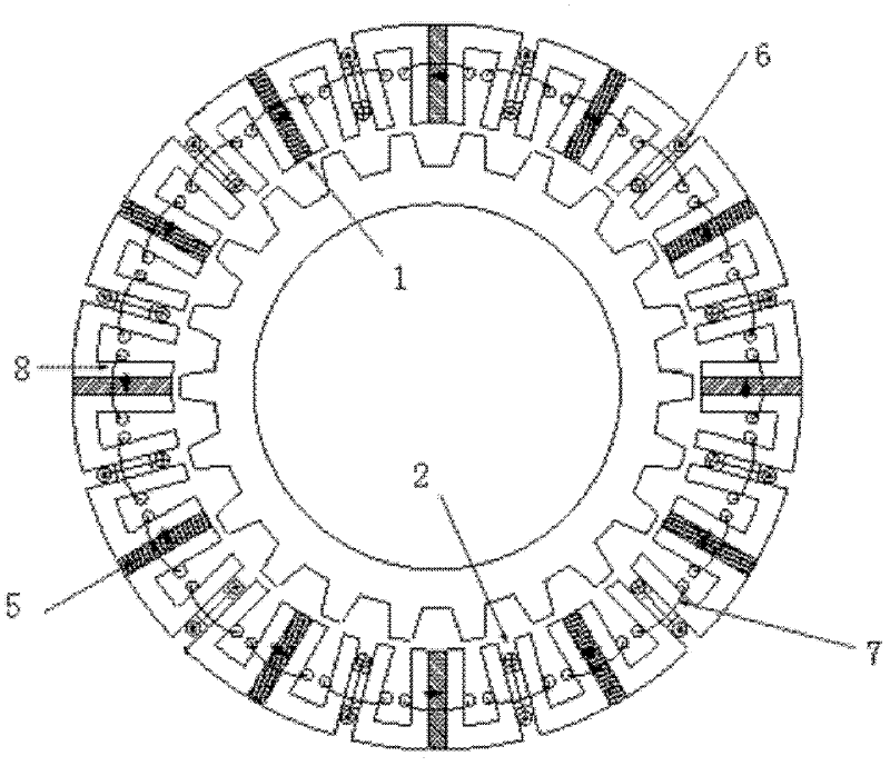
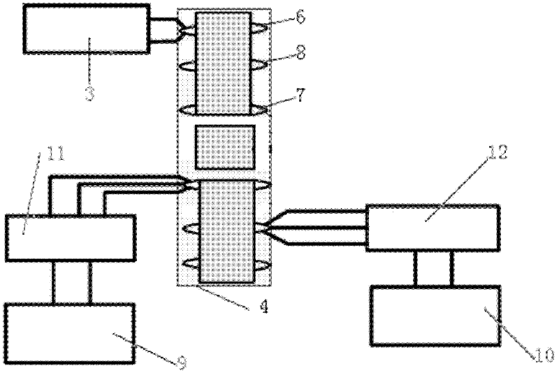
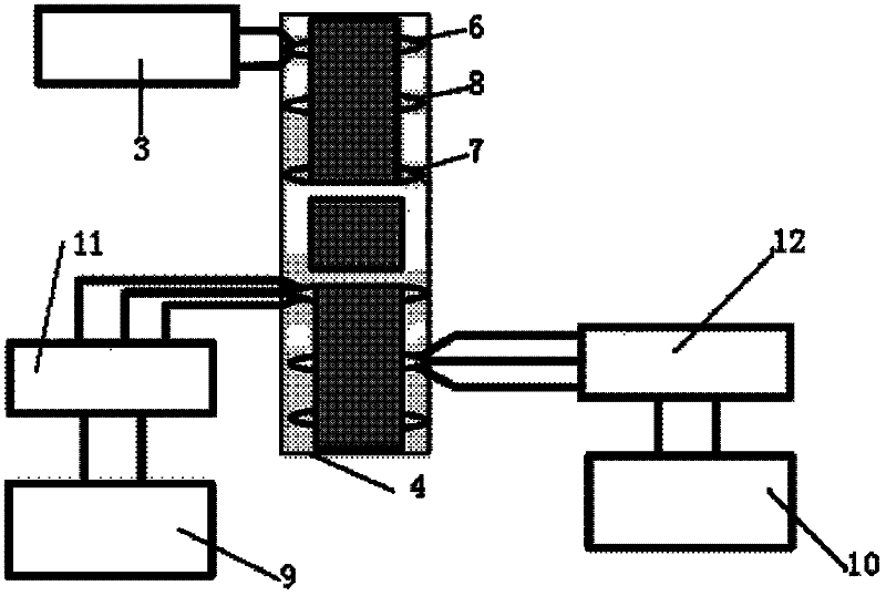
[0022] Such as Figure 1-2 The specific embodiment of the electric drive system for electric vehicles shown is: two mutually independent battery packs are respectively the first battery pack 9 and the second battery pack 10, the first battery pack 9 supplies power to the first control circuit 11, and the second battery pack 9 supplies power to the first control circuit 11. The battery pack 10 supplies power to the second control circuit 12. The first control circuit 11 and the second control circuit 12 are independent of each other and both are power conversion circuits. The armature winding 8, wherein the first three-phase armature winding 7 is set on the electric excitation tooth 2 provided with the electric excitation coil, the second three-phase armature winding 8 is set on the permanent magnet tooth 1 of the permanent magnet 5, and the DC ...


PUM


Abstract

The invention discloses an electric driving system for an electric vehicle and a control method of the electric driving system. The electric driving system comprises two sets of control circuits, two groups of battery packs, a direct-current excitation power supply and a stator permanent magnetic multiphase armature winding redundancy motor. The control method of the electric driving system for the electric vehicle comprises the steps: when the electric vehicle is started, accelerated and climbs a slope, two sets of armature windings work in an electric-electric mode; during normal operation, if stored energy of the two groups of battery packs is insufficient, the two sets of armature windings work in the electric-electric mode, if the stored energy of the two sets of battery packs is not enough and the electric vehicle does not need providing large torque, the two sets of multiphase armature windings work in a power-generating-electric working mode; during high-speed operation, a reverse excitation current is led; during speed reduction and brake, the two steps of multiphase armature windings work in the power-generating-power mode; and during fault-tolerant processing, the multiphase armature windings work by depending on a normal channel. The combination of the electric driving system and the control method thereof ensures that the vehicle can normally run under multiple conditions.

Description

technical field [0001] The patent of the present invention relates to an electric drive system for electric vehicles and its control method. The electric drive system for electric vehicles is an electric drive system using a stator permanent magnet type multi-phase double armature winding redundant motor. The electric drive system for electric vehicles The control method of the system adjusts the torque-speed characteristic of the motor through different working modes. Background technique [0002] At present, the sustainable development of the automobile industry is facing two major problems: one is environmental pollution, and the other is lack of oil resources. Therefore, energy saving and environmental protection have become two major themes in the development of the global automobile industry. Countries are also scrambling to carry out the research and development and industrialization of green and environment-friendly vehicles-electric vehicles, in which the motor and...

Claims


Application Information

Patent Timeline
Patent Type & Authority Applications(China)
IPC IPC(8): B60L15/00H02K11/00H02K3/18H02P7/00H02P9/14
CPCY02T10/64
Inventor 花为柯海波程明
Owner SOUTHEAST UNIV
Learn More