Drying room for tentering boarding machine

A tenter setting machine and drying room technology, applied in heating/cooling fabrics, textiles and papermaking, fabric surface trimming, etc., can solve the problems of poor fabric quality, poor effect, low temperature, etc., achieve good effect and reduce temperature Gradient distribution, uniform drying effect

Inactive Publication Date: 2008-03-19
JIANGSU HAIDA DYEING & PRINTING MACHINERY
View PDF0 Cites 17 Cited by
  • Summary
  • Abstract
  • Description
  • Claims
  • Application Information

AI Technical Summary

Problems solved by technology

[0002] After the original gray cloth is processed and formed, it must be stretched in order to become a fabric for production. In order to prevent the gray cloth from being torn under local stress during stretching, it needs to be dipped in glue. Therefore, when stretching, it is necessary to do Drying and setting treatment, the existing drying method adopts the method of hot roller, that is, the gray cloth impregnated with tenter is wound on the rotating high-temperature hot roller to realize drying. This kind of drying structure is simple, but the temperature of the side close to the hot roller High, the gray cloth dries quickly, and the other side of the gray cloth is low in temperature and dries slowly, so the effect of shaping is not good, and the quality of the cloth after shaping is poor

Method used


Image

  • Drying room for tentering boarding machine

Examples


Embodiment Construction

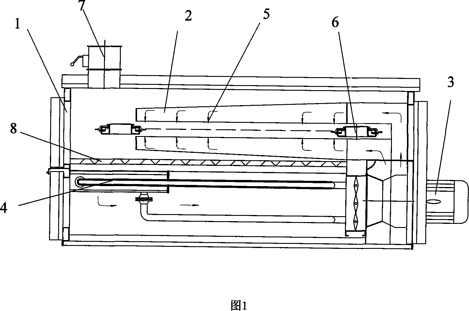
[0015] The present invention will be described in detail below with reference to the accompanying drawings. As shown in Figure 1, it includes a drying room box 1, a heating device composed of a spray pipe 2, a circulating fan 3, and a radiator 4, and a conveyor belt is arranged in the drying room box. 6. The air blowing pipe 2 includes an upper air blowing pipe and a lower air blowing pipe. The air blowing nozzles 5 are processed on the air blowing pipes, and the air blowing nozzles 5 on the two air blowing pipes are facing the conveyor belt 6 and arranged oppositely. An exhaust port 7 is also provided at the upper end of the drying room box 1, and a layer of filter screen 8 is also provided in the drying room box 1, and the filter screen 8 is located at the lower end of the lower air blowing pipe.

[0016] The heat transfer medium in the radiator 4 is oil, and water can also be selected. When in use, connect the cloth to the transmission belt 6, and the radiator 4 is connected to...


PUM


Abstract

The present invention discloses a drying room of a stenter setting machine, and comprises a drying room box body and a heating device, wherein, a belt conveyor is arranged in the drying room box body, and the heating device is arranged at the upper end and the lower end of the belt conveyor; the heating device comprises a spraying tube, a cycle air blower and a heat sink, the spraying tube is arranged at the upper end and the lower end of the belt conveyor, and the heat quantity emitted from the heat sink is transported to an air jetting tube through the cycle air blower; the heat transfer medium of the heat sink adopts oil or water; the air jetting tube is provided with two air jetting tubes, one air jetting tube is an upper air jetting tube arranged at the upper end of the belt conveyor, the other air jetting tube is a lower air jetting tube arranged at the lower end of the belt conveyor, and a layer of filter mesh is arranged at the lower end of the lower air jetting tube. Compared with the prior art, the present invention has the advantages that the drying is evener, and the drying and the setting effects are good.

Description

Technical field [0001] The invention relates to a textile machine drying room for drying and setting fabrics, in particular to a stenter setting machine drying room. Background technique [0002] After the original grey fabric is processed and formed, to become the produced fabric, it must go through tentering. In order to prevent the partially stressed grey fabric from tearing during tentering, it needs to be dipped during tentering. Therefore, when tentering, it also needs to do Drying and shaping treatment, the existing drying adopts a hot roller method, that is, the gray fabric of the dipped stenter is wound on a rotating high temperature hot roller to achieve drying. This drying structure is simple, but it is close to the temperature of one side of the hot roller High, the grey fabric dries quickly, and the other side of the grey fabric has a low temperature and dries slowly, so the shaping effect is not good, and the quality of the finished fabric is poor. Summary of the i...

Claims


Application Information

Patent Timeline
Patent Type & Authority Applications(China)
IPC IPC(8): D06C7/02D06C3/00
Inventor 陈丽洁
Owner JIANGSU HAIDA DYEING & PRINTING MACHINERY
Why Eureka
Try Eureka