A fuel cell stack with cross-cocurrent-convection comprehensive optimization characteristics

A fuel cell stack and battery unit technology, applied in fuel cells, fuel cell groups, circuits, etc., can solve the problems of reducing fluid distribution quality, unfavorable stack temperature, temperature rise, etc., and achieve the effect required by simple component processing

Active Publication Date: 2019-04-16
JIANGSU UNIV OF SCI & TECH
View PDF8 Cites 0 Cited by
  • Summary
  • Abstract
  • Description
  • Claims
  • Application Information

AI Technical Summary

Problems solved by technology

However, it should be pointed out that since the fuel and air main pipes are closely distributed on the same side of the stack, it is difficult to ensure the total inlet pipe under the parallel flow model, except for the sealing problem between adjacent fuel and air main pipes. The cross-sectional area is always smaller than the cross-sectional area of ​​the outlet main pipe, which will greatly reduce the fluid distribution quality of the fluid between the battery cells (stack level)
In addition, the following typical features are also obtained by referring to the currently reported fuel cell stack structural design schemes: 1) In general stack design, the cathode and anode connectors often use the same connector shape design, which often fails to combine fuel and anode. The different flow and electrochemical working characteristics of the air side are designed; 2) the general stack design often adopts the scheme of a single set of air flow channels, which is not conducive to the uniform distribution of the stack temperature. The research results show that due to the high molar mass of the air, The utilization rate is low, so the air flow is the main heat-carrying fluid inside the stack, and the temperature rises sharply along the direction of the air flow

Method used


Image

  • A fuel cell stack with cross-cocurrent-convection comprehensive optimization characteristics
  • A fuel cell stack with cross-cocurrent-convection comprehensive optimization characteristics
  • A fuel cell stack with cross-cocurrent-convection comprehensive optimization characteristics

Examples


Embodiment Construction

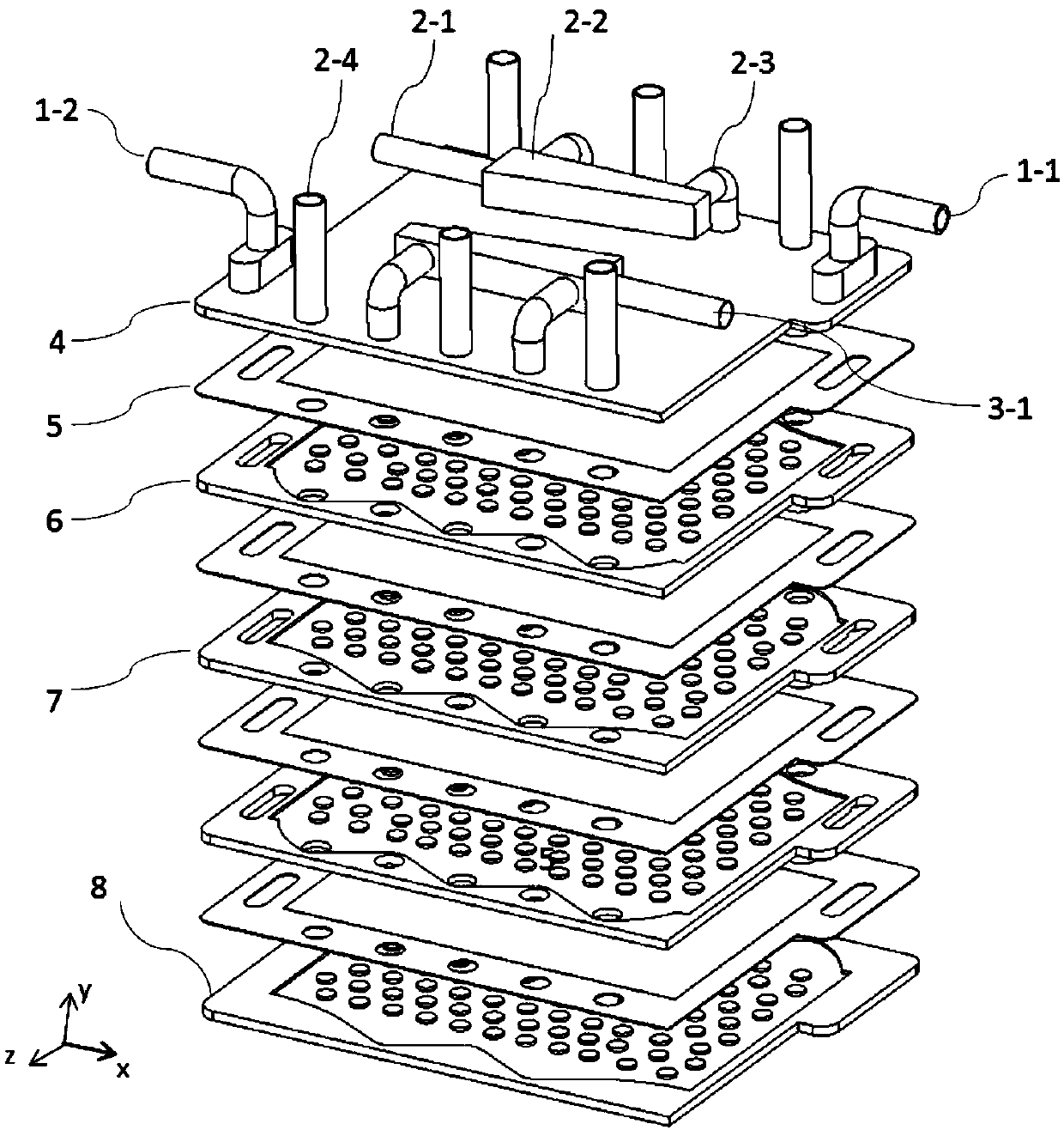
[0031] See figure 1 and figure 2 As shown, the present invention discloses a fuel cell stack with cross-cocurrent-convection integrated optimization features, including a top cover 4, a bottom cover 8, and a plurality of plate-shaped SOFCs stacked between the top cover 4 and the bottom cover 8. Battery unit 5. A connecting piece is sandwiched between the two adjacent SOFC battery cells 5, wherein the connecting piece is divided into an odd layer connecting piece 6 and an even layer connecting piece according to the odd and even numbers counted from top to bottom. 7.

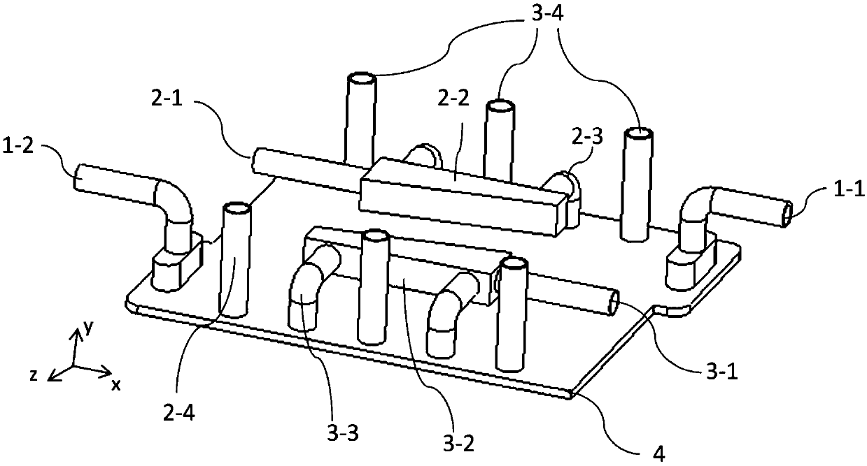
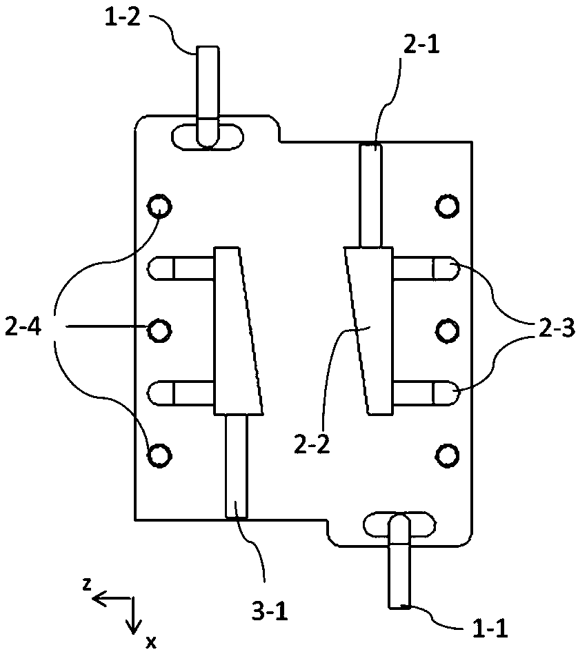
[0032] The top cover 4 is provided with a fuel outlet main pipe 1-2, a fuel inlet main pipe 1-1, a first air flow channel inlet 2-1, and a first trapezoidal distributor 2-2 connected to the first air flow channel inlet , The first air flow path inlet main pipe 2-3, the first air flow path outlet tail gas main pipe 2-4, the second air flow path inlet 3-1, the second trapezoidal distributor connected to the second a...


PUM


Abstract

The invention discloses a fuel cell stack with the comprehensive characteristics of intersecting-parallel-convective flow, comprising: fuel inlet and outlet main pipes, two sets of air inlet and outlet main pipe flow channels, stack top cover, battery unit, and connectors , bottom cover. The designed fuel outlet and inlet main pipes and air outlet and inlet main pipes are respectively arranged on different sides, the fuel side uses parallel serpentine flow channels, and the air side adopts discrete columnar linear flow channels, thereby forming a parallel flow between fuel and air. Convective and convective combined flow patterns. Two sets of air main pipes are arranged opposite to each other. The first set of air main pipes supplies air to single-layer fuel cell units, and the second set of air main pipes supplies air to double-layer battery units. Adjacent battery cells flow relatively, while the first One group of air inlet (outlet) main pipes and the second group of air out (in) main pipes are arranged alternately to ensure good heat exchange. Except for the top cover, all the connectors in the stack have the same structure, so as to meet the requirements of performance improvement and processing simplification.

Description

Technical field [0001] The invention relates to the field of solid oxide fuel cells. Background technique [0002] A fuel cell is a power generation device that directly converts the chemical energy of reactants into electrical energy. As a high-efficiency, clean and stable performance energy technology, its biggest advantage compared with traditional power generation is to avoid the combustion process and directly convert the chemical energy of the fuel into output electrical energy, and its energy conversion efficiency is not affected by the "Carnot cycle" limits. [0003] Solid oxide fuel cell (SOFC) is one of the most commercialized types of fuel cells. Its main advantages include: a fuel efficiency of up to 50-60%. The products are mainly water and high-quality waste heat. The total efficiency of secondary utilization can be as high as 80%; the output power is large, the operation is stable and there is no noise; the fuel source is flexible, not only suitable for hydrogen, c...

Claims


Application Information

Patent Timeline
Patent Type & Authority Patents(China)
IPC IPC(8): H01M8/24H01M8/2465H01M8/04089
CPCH01M8/04089H01M8/24H01M8/2465Y02E60/50
Inventor 陈代芬章心怡徐雨胡彪
Owner JIANGSU UNIV OF SCI & TECH
Why Eureka
Try Eureka