
Oil-saving device

A fuel-saving and pipeline technology, applied in the charging system, internal combustion piston engine, engine components, etc., can solve the problems of shortening, complex structure, high cost, etc., to improve combustion efficiency, prolong engine life, and reduce exhaust gas. Effect

Inactive Publication Date: 2008-03-19
王金龙
View PDF0 Cites 3 Cited by
  • Summary
  • Abstract
  • Description
  • Claims
  • Application Information

AI Technical Summary

Problems solved by technology

[0004] However, the disadvantages of the existing fuel economizers are: the structure of the product is quite complicated, resulting in high cost, and the existing fuel economizers are not easy to install and disassemble, and the future cleaning and maintenance costs will remain high, so that the market acceptance is not good. In addition, the existing fuel economizer cannot remove impurities from the oil conveyed in the oil pipe, so that the service life of the car engine is greatly shortened, so the existing fuel economizer still has defects and needs to be improved

Method used


Image

  • Oil-saving device
  • Oil-saving device
  • Oil-saving device

Examples


Embodiment Construction

[0036] While the invention will be fully described with reference to the accompanying drawings, which contain preferred embodiments of the invention, it should be understood before proceeding that those skilled in the art may modify the invention described herein while still obtaining the benefits of the invention. Therefore, it should be understood that the following description is a broad disclosure for those skilled in the art, and its content is not intended to limit the present invention.

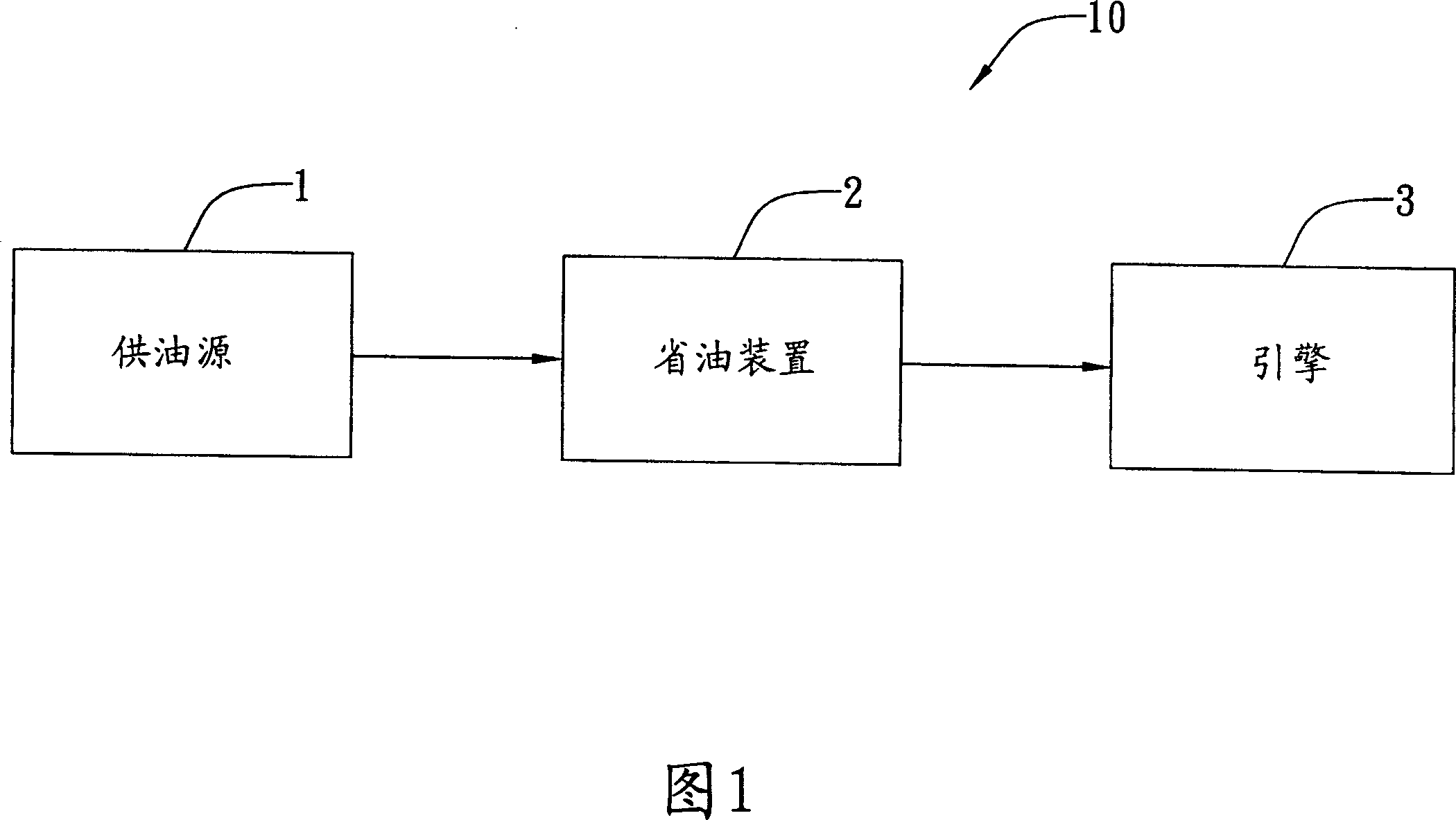
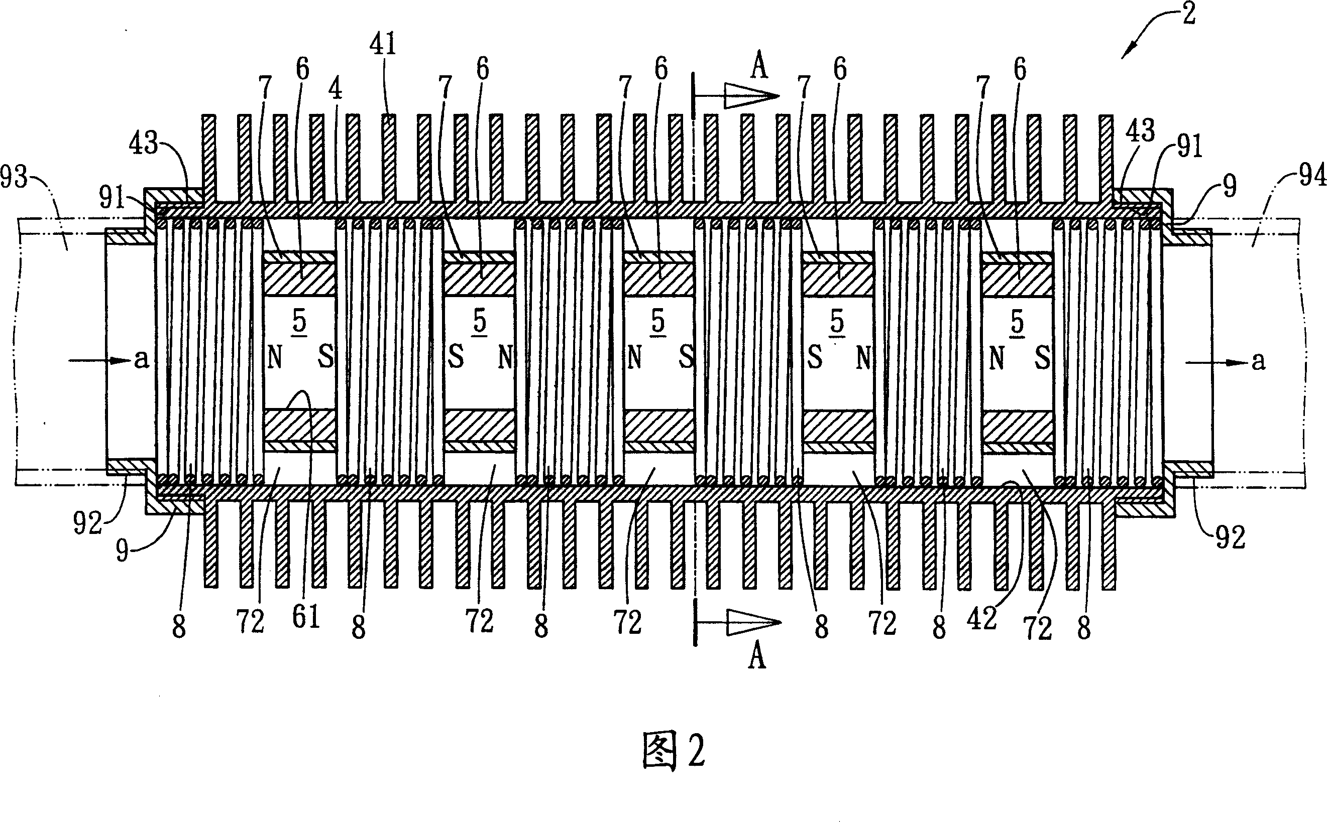
[0037] Please refer to FIG. 1 , which is a block diagram of the fuel saving device of the present invention applied to a fuel system. In this preferred embodiment, the fuel system 10 at least includes a fuel supply source 1 and an engine 3, and a fuel-saving device 2 is provided between the aforementioned fuel supply source 1 and the engine 3, and the fuel-saving device 2 does not need to provide electricity , and its composition structure is simple, wherein each component can be easil...


PUM


Abstract

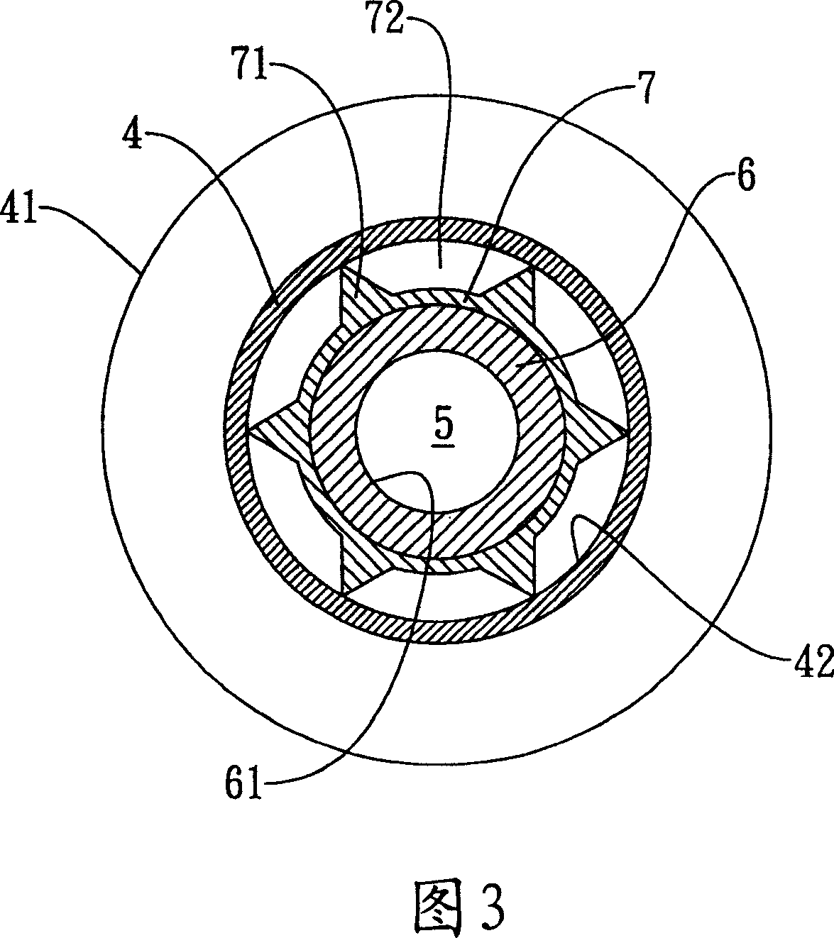
The invention relates to a fuel saving device, and comprises a pipeline with conduction elements, a cavity is arranged on the conduction elements; a plurality of magnetic elements which have through holes, are wrapped in the metal material elements with a plurality of gaps, and are arranged in the cavity of the pipeline; and a plurality of elastic elements which are arranged in the cavity of the pipeline and at the both sides of the magnetic elements. Another fuel saving device, and the device comprises: pipeline with conduction elements, a cavity is arranged on the condunction elements; a plurality of magnetic elements which have through holes, are wrapped in the metal material elements with a plurality of gaps, and are arranged in the cavity of the pipeline; a plurality of elastic elements, and are arranged in the cavity of the pipeline and at the both sides of the magnetic elements. And a delivery pipe which is arranged in the cavity of the pipeline, and penetrated through the magnetic elements and the elastic elements. The invention can enable the fuel temperature to be increased to the ignition point in advance for the convenience of the complete combustion of the engine ignition, to reduce the production of waste foul gas.

Description

technical field [0001] The invention relates to a fuel-saving device, especially a fuel-saving device that does not need to provide electric power, has a simple structure, is easy to clean and maintain, and has low cost. Background technique [0002] Under the trend of energy saving and environmental protection, a fuel economizer is generally installed before fuel enters the car's engine to increase horsepower, reduce carbon deposits, and save fuel. [0003] The existing fuel economizer is a structure that can release far-infrared rays or magnetic energy, so as to refine and activate the fuel molecules transported in the oil pipe, thereby improving the combustion efficiency of fuel and achieving the purpose of saving fuel. [0004] However, the disadvantages of the existing fuel economizers are: the structure of the product is quite complicated, resulting in high cost, and the existing fuel economizers are not easy to install and disassemble, and the cleaning and maintenance...

Claims


Application Information

Patent Timeline
IPC IPC(8): F02M27/04F02M37/22
CPCY02T10/126Y02T10/12
Inventor 王锦郎
Owner 王金龙
Learn More