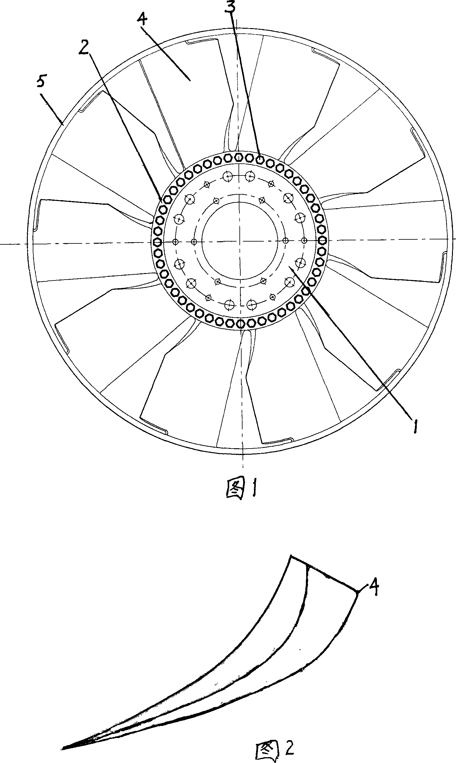
Automobile engine cooling fan
A technology for automobile engines and cooling fans, which is applied in the direction of machines/engines, liquid fuel engines, mechanical equipment, etc. It can solve the problems of reducing the service life of the fan, unbalanced force on the blades, and affecting the performance of the fan, so as to improve the air volume and air pressure. Improve the rigidity and strength, increase the effect of the effective work area
- Summary
- Abstract
- Description
- Claims
- Application Information
AI Technical Summary
Problems solved by technology
Method used
Image
Examples
Embodiment 1
[0014] Embodiment 1: Refer to Figures 1 and 2, an automobile engine cooling fan, including a tray 1, a hub 2 and ribs 3, and blades 4. The impeller is composed of a tray 1, a hub 2, and blades 4, and the blades 4 are airfoil-shaped The cross-section blades, the blade 4 and the hub 2 are integrally formed, the chord length ratio between the inner and outer diameters of each blade 4 is 1:1.1, the angle between the line of gravity center of each section of the blade 4 and the radial straight line is 5°, and each section of the blade 4 The projection distance of the center of gravity line on the rotating shaft is controlled at 2% of the impeller diameter, which is spatially twisted. The connection between the blade 4 and the hub 2 adopts a circular arc transition. shape. The blade 4 is connected with the guide ring 5.
Embodiment 2
[0015] Embodiment 2: Refer to Figures 1 and 2, an automobile engine cooling fan, including a tray 1, a hub 2 and ribs 3, and blades 4. The impeller is composed of a tray 1, a hub 2, and blades 4, and the blades 4 are airfoil-shaped Cross-section blades, blade 4 and hub 2 are integrally formed, the chord length ratio between the inner and outer diameters of each blade 4 is 1:1.5, the angle between the line of gravity center of each section of blade 4 and the radial line is 25°, and the section of blade 4 The projection distance of the center of gravity line on the rotating shaft is controlled at 8% of the diameter of the impeller, which is spatially twisted. The connection between the blade 4 and the hub 2 adopts a circular arc transition. Others are the same as in Example 1.
Embodiment 3
[0016] Embodiment 3: Referring to Figures 1 and 2, an automobile engine cooling fan includes a tray 1, a hub 2 and ribs 3, and blades 4. The impeller is composed of a tray 1, a hub 2, and blades 4, and the blades 4 are airfoil-shaped Cross-section blades, blade 4 and hub 2 are integrally formed, the ratio of chord length between the inner and outer diameters of each blade 4 is 1:1.3, the angle between the line of gravity center of each section of blade 4 and the radial line is 15°, each section of blade 4 The projection distance of the center of gravity line on the rotating shaft is controlled at 5% of the diameter of the impeller, which is spatially twisted. The connection between the blade 4 and the hub 2 adopts a circular arc transition. Others are the same as in Example 1.
PUM
 Abstract
Description
Claims
Application Information
 - R&D
- Intellectual Property
- Life Sciences
- Materials
- Tech Scout
- Unparalleled Data Quality
- Higher Quality Content
- 60% Fewer Hallucinations
Browse by: Latest US Patents, China's latest patents, Technical Efficacy Thesaurus, Application Domain, Technology Topic, Popular Technical Reports.
© 2025 PatSnap. All rights reserved.Legal|Privacy policy|Modern Slavery Act Transparency Statement|Sitemap|About US| Contact US: help@patsnap.com

