Gearwheel unit, transmission having gearwheel unit and gearwheel manufacturing method

A technology of gear sets and gears, which is applied in the field of gear sets, can solve the problems of inability to form positioning parts of variable speed gears, failure to ensure target strength, poor manufacturability, etc., to prevent embedding of spray particles, ensure strength, and shorten axial length Effect

Inactive Publication Date: 2008-03-19
AICHI MASCH IND CO LTD
View PDF1 Cites 2 Cited by
  • Summary
  • Abstract
  • Description
  • Claims
  • Application Information

AI Technical Summary

Problems solved by technology

[0004] However, in recent years, with the development of multi-stage and high-speed gearboxes, the transmission gears have been miniaturized, and positioning parts cannot be formed on the side surfaces of the transmission gears. Situation for targeting
In this case, if the transmission gear is formed as helical teeth, and the contact portion between the transmission gear and the clutch gear is wedge-shaped, the spray particles sprayed to improve the strength of the dedendum are difficult to hit the vicinity of the contact portion, and the target strength cannot be ensured. , resulting in the situation where the spray particles are embedded in the contact part
In addition, although the clutch gear can be positioned and fixed at a position separated from the transmission gear in the axial direction by a jig or the like, or the clutch gear can be integrally formed on the transmission gear, the manufacturability of the former deteriorates, while the latter device Axial upscaling

Method used


Image

  • Gearwheel unit, transmission having gearwheel unit and gearwheel manufacturing method
  • Gearwheel unit, transmission having gearwheel unit and gearwheel manufacturing method
  • Gearwheel unit, transmission having gearwheel unit and gearwheel manufacturing method

Examples


Embodiment 1

[0025] Hereinafter, a first embodiment of the present invention will be described with reference to the drawings.

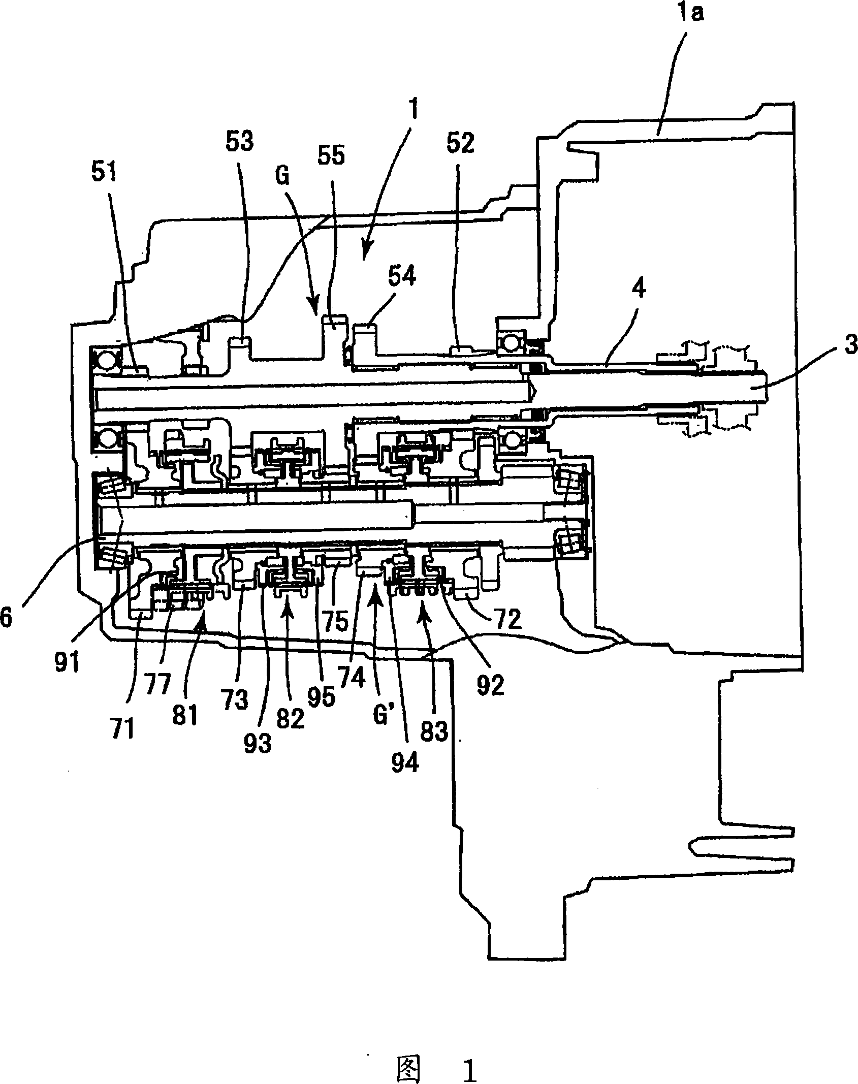
[0026] FIG. 1 is a configuration diagram showing a schematic configuration of a transmission case 1 equipped with a gear set as an embodiment of the present invention.

[0027] The gearbox 1 of the embodiment has a first input shaft 3, a second input shaft 4, and an output shaft 6. The first input shaft 3 is connected to a crankshaft of an engine not shown in the figure through a first clutch, and the second input shaft 4 Connected to the crankshaft of the engine not shown in the figure through the second clutch, and coaxially overlaid on the first input shaft 3, the output shaft 6 is connected to the first input shaft 3 and the second input shaft 4 through the transmission mechanism TM .

[0028] The transmission mechanism TM is composed of a driving gear set G, a driven gear set G′ and a synchronizing device 80. The driving gear set G is fixedly arranged on th...

Embodiment 2

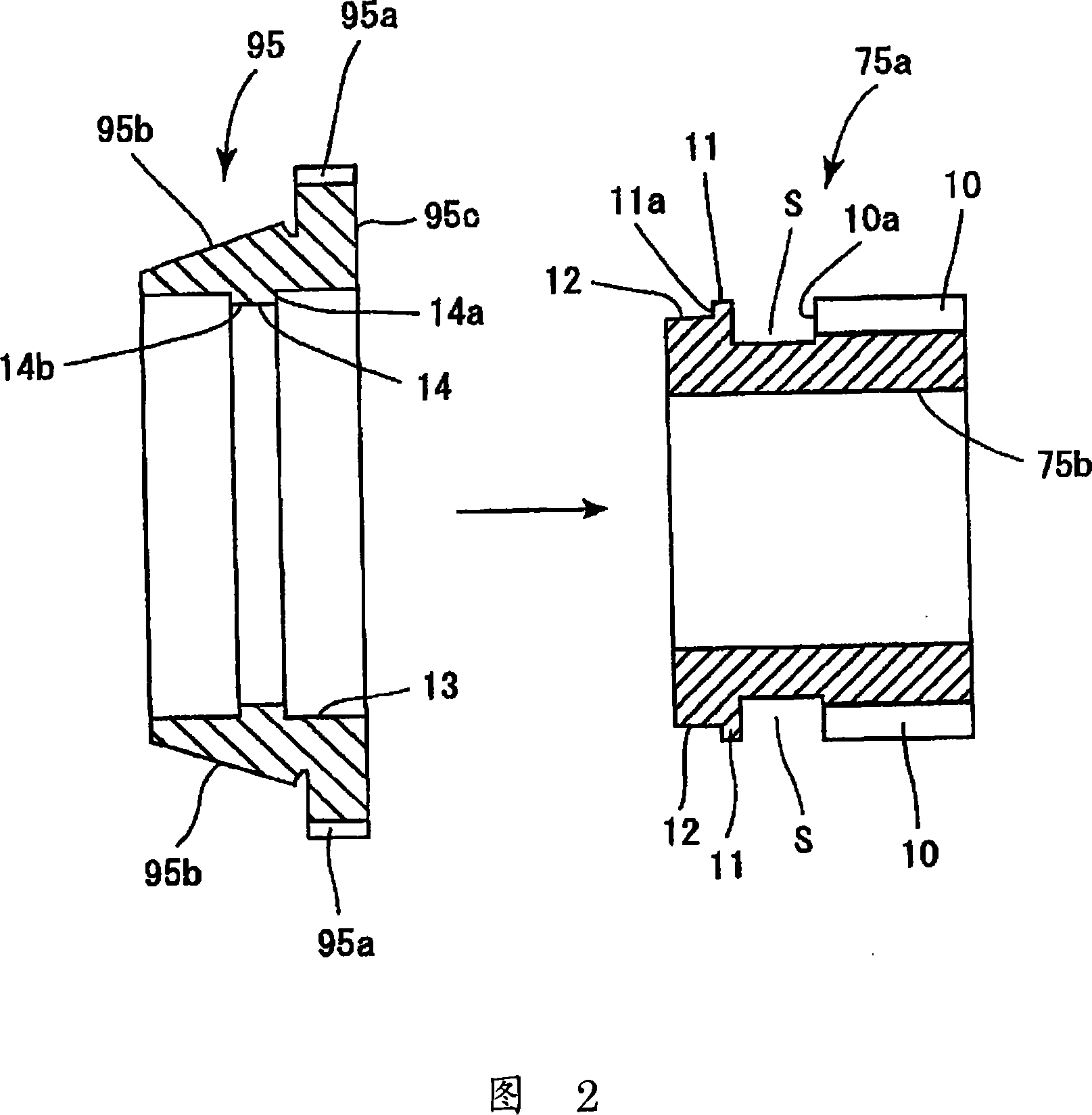
[0045] Hereinafter, what is shown in the exploded view of FIG. 4 and the assembled view of FIG. 5 is the second embodiment. In this second embodiment, the best method of positioning the clutch gear 95 well in the gearbox 1 of FIG. 1 is also adopted. The gear body 75 a of the driven gear 75 for the small gear, that is, the 5th speed has a structure in which the clutch gear 95 is assembled and fixed to the driven gear 75 by shortening the axial length.

[0046] In the second embodiment, a space S is formed on the left side of the tooth portion 10 of the gear main body 75a in the drawing, and protrudes radially outward from the left side of the space S in the drawing to the left end surface 75c of the gear main body 75a. Protruding portion 11 is integrally formed. In the gear main body 75 a , the vertical surface at the right end of the protruding portion 11 becomes the abutment surface 11 a against which the clutch gear 95 abuts, and the outer peripheral surface of the protruding...

Embodiment 3

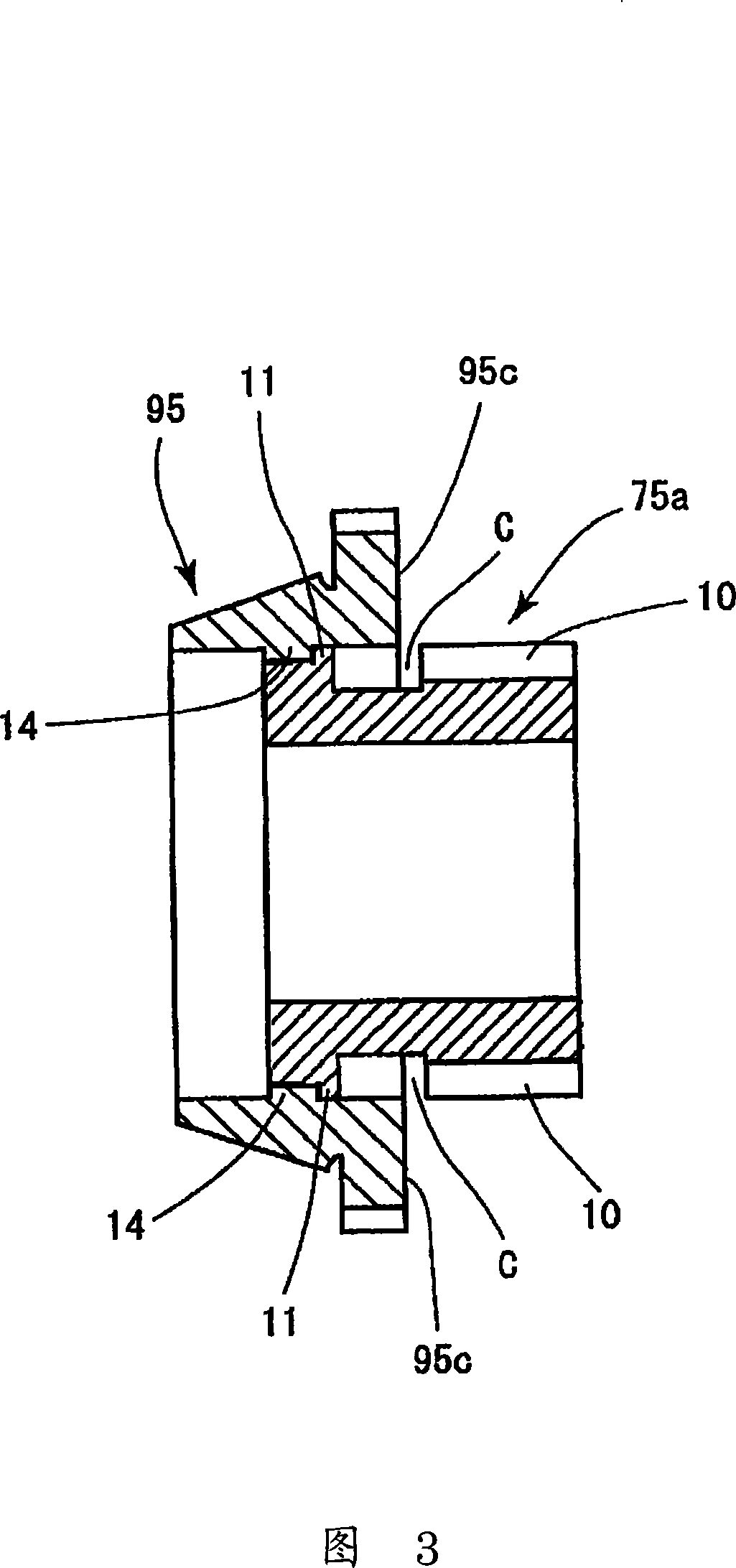
[0050] Hereinafter, the third embodiment is shown by the exploded view of FIG. 6 and the assembled view of FIG. 7 .

[0051] The gear main body 75a of the third embodiment has the same shape as the gear main body 75a of the second embodiment, and a space S is formed on the left side of the gear end surface 10a of the outer peripheral tooth portion 10 in the drawing, and a space S is formed on the left side of the space S in the drawing. A protrusion 11 is formed extending to the left end surface 75c and protruding outward in the radial direction. The outer periphery of the protrusion 11 becomes the fitting surface 12. In the example, it is set as the contact surface 11a on the side of the gear main body 75a.

[0052] On the other hand, in the clutch gear 95, an inner protrusion 14 is integrally formed on the inner peripheral side of the tapered portion 95b formed on the outer periphery to protrude in the inner diameter direction. The inner periphery of the right engaging hole...


PUM


Abstract

A gearwheel unit includes a gear body and a clutch gear. The gear body includes a gear part and a positioning part. The gear part is configured and arranged to transmit rotation of a rotational shaft with a prescribed change gear ratio. The positioning part is integrally formed with the gear part at a position spaced apart from the gear part by a prescribed distance in an axial direction so that a prescribed open space is formed between the positioning part and the gear part. The clutch gear is fixedly coupled to the gear body as being positioned with respect to the gear body by the positioning part so that at least a part of the clutch gear overlaps the prescribed open space formed between the positioning part and the gear part of the gear body when viewed in a radial direction.

Description

technical field [0001] The invention relates to a gear set, a gearbox with the gear set and a manufacturing method of the gear set. Background technique [0002] Conventionally, as such a gear set, a gear set having a clutch gear engageable with an internal spline of a coupling sleeve of a synchronization mechanism has been proposed. In this gear set, after the clutch gear is brought into contact with a positioning portion formed on the side surface of the transmission gear for axial positioning, it is attached and fixed by welding or the like. [0003] Patent Document 1: Japanese Patent Laid-Open No. 2002-174261 [0004] However, in recent years, with the development of multi-stage and high-speed gearboxes, the transmission gears have been miniaturized, and positioning parts cannot be formed on the side surfaces of the transmission gears. The situation where positioning is performed. In this case, if the transmission gear is formed as helical teeth, and the contact porti...

Claims


Application Information

Patent Timeline
Patent Type & Authority Applications(China)
IPC IPC(8): F16H55/02F16H55/17F16H3/12F16H55/06B23F17/00
CPCF16H55/171F16D23/025F16D2023/0637F16H55/17F16D2250/00F16D23/06F16D2023/0625Y10T29/49464Y10T74/19242Y10T74/19893
Inventor 铃村靖后藤正
Owner AICHI MASCH IND CO LTD
Why Eureka
Try Eureka