
Stray light test instrument

A tester and stray light technology, which is applied in the field of stray light tester, can solve the problems of guide rail shaking, large resistance, and lower measurement accuracy, and achieve the effects of stable operation, small measurement error, and small translation and rotation resistance

Inactive Publication Date: 2008-03-19
CHANGCHUN INST OF OPTICS FINE MECHANICS & PHYSICS CHINESE ACAD OF SCI
View PDF0 Cites 18 Cited by
  • Summary
  • Abstract
  • Description
  • Claims
  • Application Information

AI Technical Summary

Problems solved by technology

The problem with this stray light tester is that the detector can only move in a long distance in two dimensions (X, Y) in a straight line, and in the direction of the Y axis, it can only be moved slightly by the adjustment frame, so it is only suitable for the image plane. Small optical system stray light test; since the sliding contact is used between the adjustment frame and the guide rail, the distance between the sliding surfaces is even small, and the grease will solidify after a long time, so the resistance is large when moving, and the guide rail is easy to shake, often causing The detector shakes a lot, which brings measurement errors. The larger the volume and weight of the optical system under test, the greater the error; measurement accuracy

Method used


Image

  • Stray light test instrument
  • Stray light test instrument

Examples


Embodiment Construction

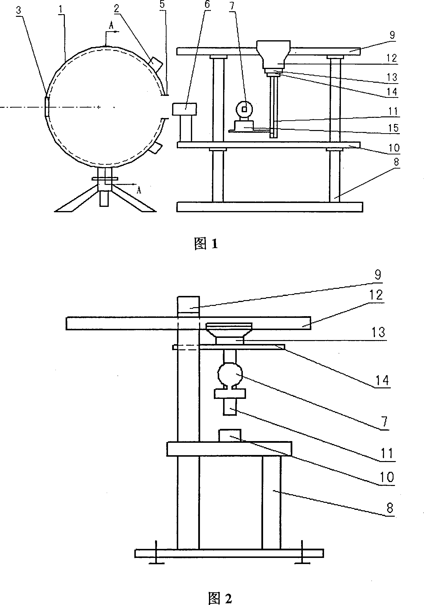
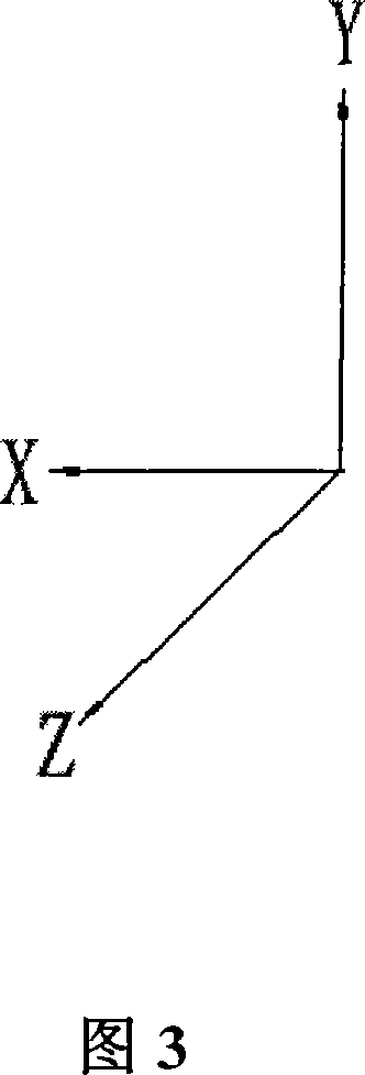
[0012] As shown in Figure 1, the stray light tester of the present invention includes an integrating sphere 1, a light source 2, a target plate 3, a variable diaphragm 5, a detector 7, an adjustment frame 13 and a four-dimensional moving mechanism; the detector 7 is in a four-dimensional moving mechanism It can do three-dimensional (X, Y, Z) translation, and can rotate 360 ​​degrees around the Y axis in the horizontal direction. When testing the uniformity of the image surface illuminance and measuring the stray light coefficient of the optical system of the large image surface, the detector 7 can be translated in the three-dimensional (X, Y, Z) direction to gradually test the entire image surface. By rotating the adjusting frame 13 around the Y-axis direction guide 11, the optical system of the spherical image surface can be tested for stray light.

[0013] The connection between the X-axis direction guide rail, the Y-axis direction guide rail 11, the Z-axis direction guide rail ...


PUM


Abstract

The invention relates to a parasitic light test set, which comprises an integrating sphere, an optical source, a target plate, a variable optical diaphragm, a detector, an adjusting bracket, and a four-dimension travel mechanism; the detector can be translated along the three-dimension (X, Y, Z) on the four-dimension travel mechanism, and can also be rotated around the Y axle along the horizontal direction. The invention can make the uniformity test to image-plane irradiance, and can also realize the test of the optical system parasitic light factor when the image-plane is a flat surface or a spherical surface.

Description

Technical field [0001] The invention relates to a stray light tester, in particular to a stray light tester for testing the stray light coefficient of an optical lens. Background technique [0002] The stray light coefficient is a relatively important indicator for evaluating the imaging quality of optical lenses. If the stray light coefficient is large, the image contrast of the image plane will be reduced, and the low image contrast means that the transmission quality of the optical lens target is reduced, and the image quality is poor. Therefore, the accuracy of the detection result of the stray light coefficient is very important. [0003] The existing stray light tester includes an integrating sphere, a variable diaphragm, a detector, an adjustment frame, and a two-dimensional moving mechanism; the light source is installed on the integrating sphere shell, and the inner surface of the integrating sphere is coated with diffuse reflection material. The target board, the variab...

Claims


Application Information

Patent Timeline
Patent Type & Authority Applications(China)
IPC IPC(8): G01M11/00G01M11/02
Inventor 谷立山王立朋张晓辉
Owner CHANGCHUN INST OF OPTICS FINE MECHANICS & PHYSICS CHINESE ACAD OF SCI
Learn More