Amplifier and method for adding bandwidth via current injection

A technology of amplifier and bandwidth, which is applied in DC-coupled DC amplifiers, differential amplifiers, improved amplifiers to expand bandwidth, etc., and can solve problems such as device size increase and bandwidth upper limit

Active Publication Date: 2010-04-14
REALTEK SEMICON CORP
View PDF4 Cites 0 Cited by
  • Summary
  • Abstract
  • Description
  • Claims
  • Application Information

AI Technical Summary

Problems solved by technology

Also, if the parasitic capacitance value C op effect is much greater than capacitive load C load , thus reducing the capacitive load C load little effect
If the value gm is to be transduced, a device of larger size is required, but this will lead to a larger parasitic capacitance value, so the size of the device cannot be increased without limit
Thus, the relationship between gain and bandwidth creates an upper bandwidth

Method used


Image

  • Amplifier and method for adding bandwidth via current injection
  • Amplifier and method for adding bandwidth via current injection
  • Amplifier and method for adding bandwidth via current injection

Examples


Embodiment Construction

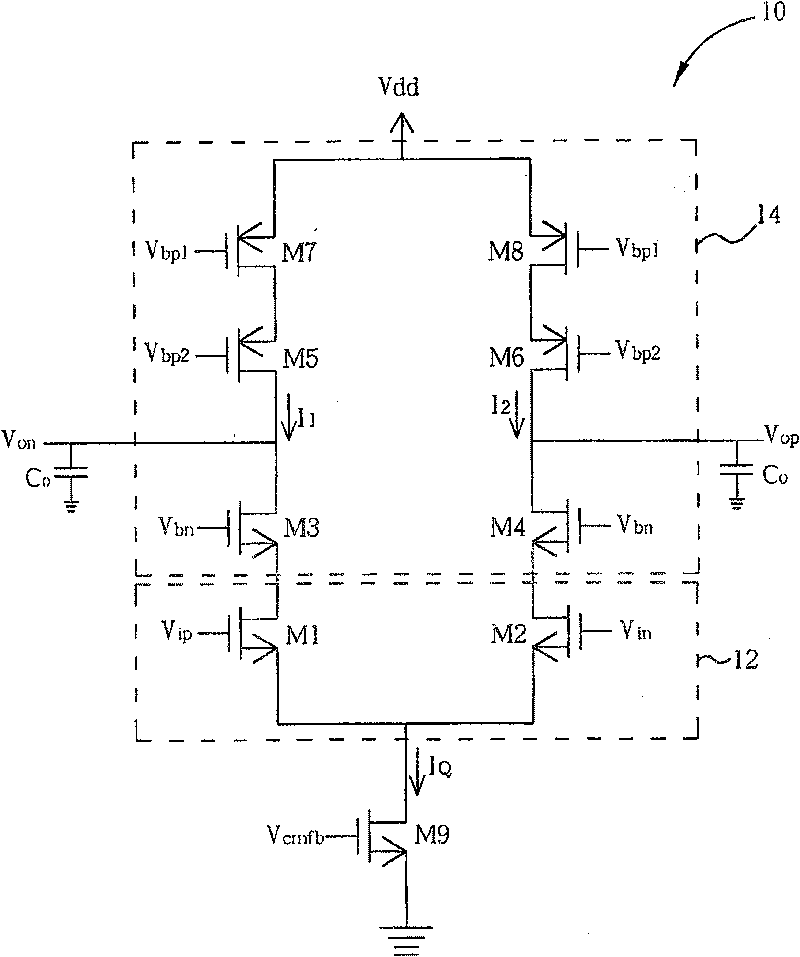
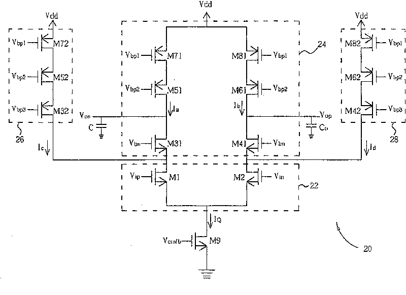
[0024] figure 2 is a schematic diagram of a first embodiment of the amplifier 20 of the present invention. Amplifier 20 can increase bandwidth and maintain high gain under current injection conditions. The amplifier 20 includes an input stage 22 and a load stage 24 . The input stage 22 includes two transistors M1 and M2, and the load stage 24 includes a plurality of transistors M31, M41, M51, M61, M71, M81. Transistor M9 is used as a current source to draw a fixed reference current I Q to control multiple currents I a -I d current value. If both transistors M1 and M2 are in the conduction state, the current I a with I c The sum of is equal to figure 1 The current shown in I 1 , while the current I b with I d The sum of is equal to figure 1 The current shown in I 2 . In one embodiment, the circuit structures of the input stage 22 and the load stage 24 are the same as figure 1 The circuit structure of the input stage 12 shown in is the same as that of the load st...


PUM


Abstract

The invention discloses an amplifier capable of increasing bandwidth by injecting current and a method thereof. The amplifier comprises an output terminal for receiving a first input signal; a load terminal coupled with the input terminal and used for outputting the first input signal; a preserved current source coupled with the input terminal and used for allowing the circulating of a fixed current; and a first current source coupled with the input terminal and used for injecting the first current into the input terminal and outputting the first output signal.

Description

technical field [0001] The invention relates to an amplifier, in particular to an amplifier with increased bandwidth and a method thereof. Background technique [0002] Operational amplifiers are one of the most widely used devices, ranging from buffers, filters, analog / digital converters to digital / analog converters. When high performance is required, such as high-speed or high-resolution, analog-to-digital converters, an operational amplifier with high gain and high bandwidth is required. [0003] see figure 1 , figure 1 is a schematic diagram of an existing amplifier 10 . The components within the amplifier 10 are arranged in a telescopic topology. Amplifier 10 includes a plurality of transistors M1-M9. Transistors M1 and M2 are transistors with the same characteristics and are used as an input stage 12 to receive an input voltage V ip with an inverted input voltage V in , and the transistors M3-M8 are used as a load stage 14, such as an active load (active load), ...

Claims


Application Information

Patent Timeline
Patent Type & Authority Patents(China)
IPC IPC(8): H03F1/42H03F3/45
Inventor 杜全平
Owner REALTEK SEMICON CORP
Why Eureka
Try Eureka