Heat radiator

A technology of cooling device and radiator, applied in cooling/ventilation/heating transformation, instrument cooling, instrument and other directions, can solve the problems of reducing the heat dissipation performance of the radiator, poor heat dissipation effect of the electronic device of the central processing unit, etc., to achieve the best heat dissipation effect of effect

Inactive Publication Date: 2008-03-19
FU ZHUN PRECISION IND SHENZHEN +1
View PDF1 Cites 24 Cited by
  • Summary
  • Abstract
  • Description
  • Claims
  • Application Information

AI Technical Summary

Problems solved by technology

If the cover is removed and the airflow generated by the fan is blown around, the heat dissipation performance of the radiator will be reduced.

Method used


Image

  • Heat radiator
  • Heat radiator
  • Heat radiator

Examples


Embodiment Construction

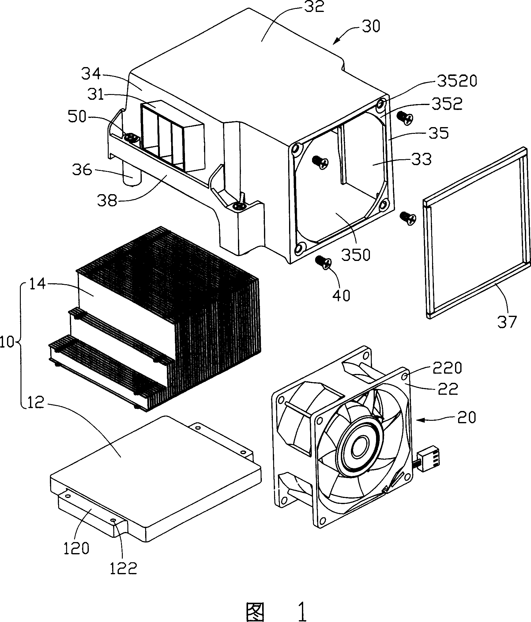
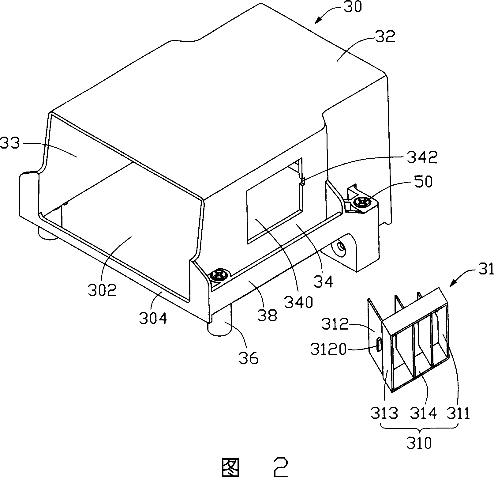
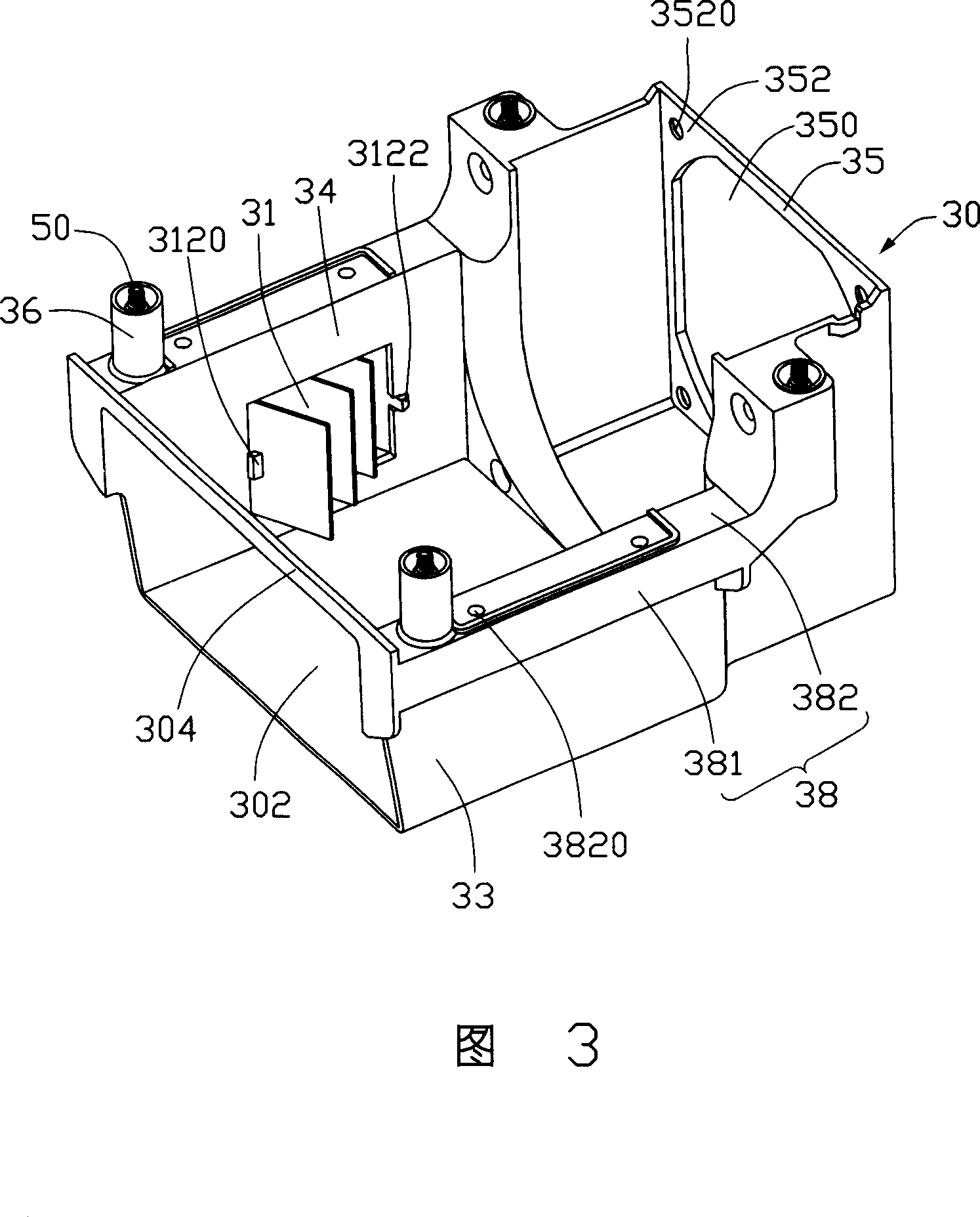
[0017] Please refer to FIG. 1 . FIG. 1 is a first embodiment of the heat sink of the present invention. The cooling device is installed on a circuit board (not shown), and includes a radiator 10, a cover 30 covering the radiator 10, a window 31 that can be installed on the cover 30, and a The fan 20 on one side of the radiator 10 .

[0018] The heat sink 10 includes a base 12 bonded to the electronic components (not shown) on the circuit board and a cooling fin group 14 placed on the base 12, the cooling fin group 14 and the base 12 Integrate by welding or gluing. The base 12 is generally arranged in the shape of a rectangular plate, and the opposite side edges of the base 12 protrude horizontally from two fixing parts 120, and each fixing part 120 is provided with a through hole 122 at both ends for the cover. 30 lock. The heat dissipation fin set 14 is composed of several heat dissipation fins to form several air passages for the forced airflow provided by the fan 20 to p...


PUM


Abstract

A heat dissipating device includes a heat dissipater and a shield. The shield encloses the heat dissipater therein to form a passage passing through the heat dissipater. The passage includes an air inlet and an air outlet; a fan is arranged at the air inlet of the shield, and a window communicating the passage and outside of the shield is arranged on the shield. The heat dissipating device can satisfy heat dissipating requirement of a center processor unit and electronic elements surrounding the center processor unit accordingly and produce good heat dissipating effect.

Description

technical field [0001] The invention relates to a heat dissipation device, in particular to a heat dissipation device used on electronic components. Background technique [0002] With the rapid development of the electronic industry, the computing speed of the electronic components in the computer has been greatly increased, and the heat generated by it has also increased sharply. How to dissipate the heat of the electronic components to ensure their normal operation has always been a must for the industry. The problem. As we all know, the central processing unit installed on the motherboard is the core of the computer system. When the computer is running, the central processing unit generates heat. Excessive heat can prevent the CPU from functioning properly. In order to effectively dissipate the heat generated by the central processing unit during operation, a cooling device in contact with the central processing unit is usually installed on the circuit board to dissipat...

Claims


Application Information

Patent Timeline
IPC IPC(8): H05K7/20H01L23/467G06F1/20G12B15/04
Inventor 龙俊李皓李涛
Owner FU ZHUN PRECISION IND SHENZHEN
Why Eureka
Try Eureka