Structure of cutting tip and saw blade including the structure

A cutting-edge and saw-blade technology, applied in the field of cutting tip structures, can solve the problems that objects cannot be cut accurately, shorten the service life of the saw blade, and degrade the strength of the steel body, achieve good cooling efficiency, simplify the manufacturing process, and prolong the service life. Effect

Inactive Publication Date: 2008-03-19
曹昶臣
View PDF0 Cites 2 Cited by
  • Summary
  • Abstract
  • Description
  • Claims
  • Application Information

AI Technical Summary

Problems solved by technology

[0005] [5] However, according to the conventional circular saw blade having the above structure, due to a synergistic action such as heat generated from the cutting tip itself and heat generated from friction of the steel body during cutting, the strength may degrade
Furthermore, as the cutting process continues, severe vibrations may be generated from the steel body due to the heat and friction applied to the steel body, so that the object cannot be cut accurately
[0006] [6] This frictional heat and overload can damage expensive saw blades and shorten their life
However, it is difficult for saw blade manufacturers to find the optimum conditions, such as time, temperature and pressure, during the sintering process for forming the optimum properties of the cutting tip segment of the saw blade

Method used


Image

  • Structure of cutting tip and saw blade including the structure
  • Structure of cutting tip and saw blade including the structure
  • Structure of cutting tip and saw blade including the structure

Examples


Embodiment Construction

[0057] [54] Next, a cutting tip and a saw blade having the cutting tip according to preferred embodiments of the present invention will be described with reference to the accompanying drawings.

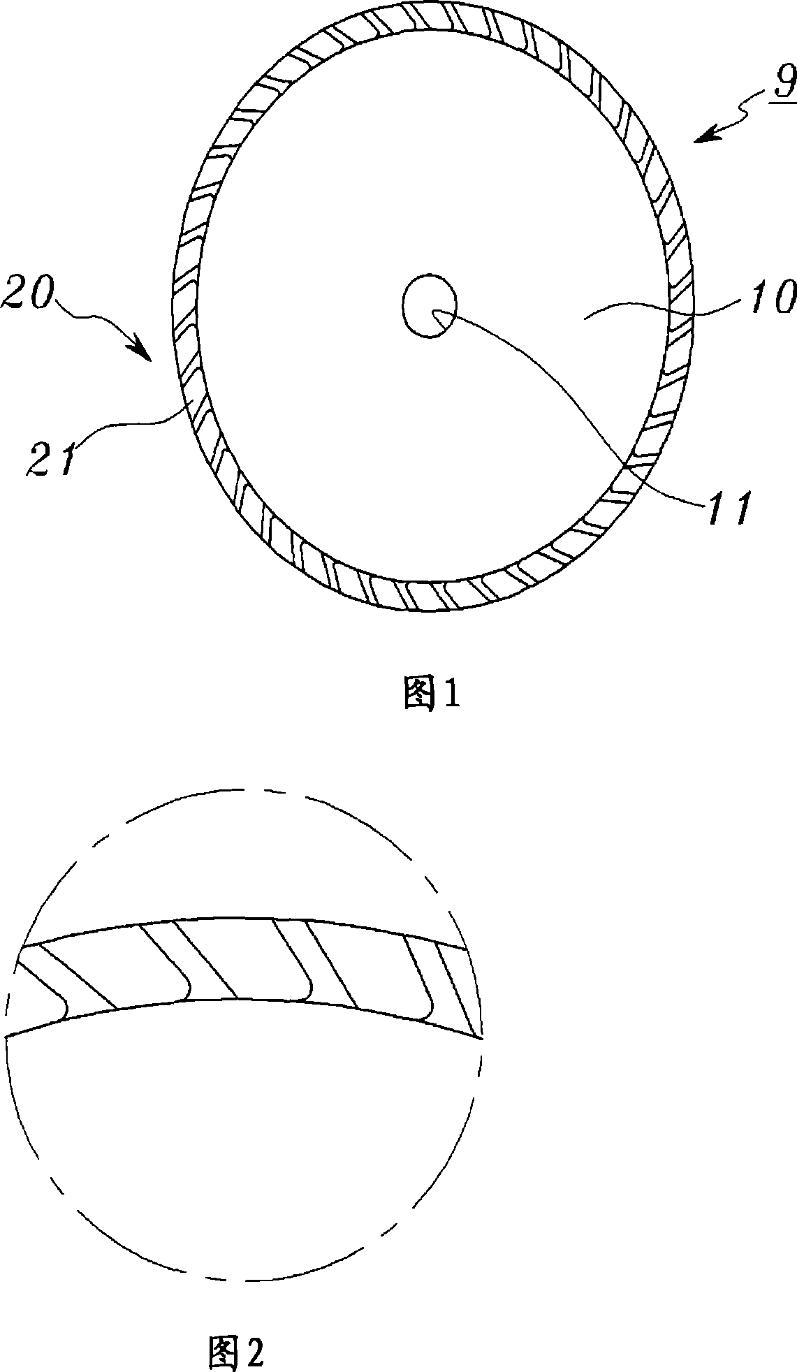
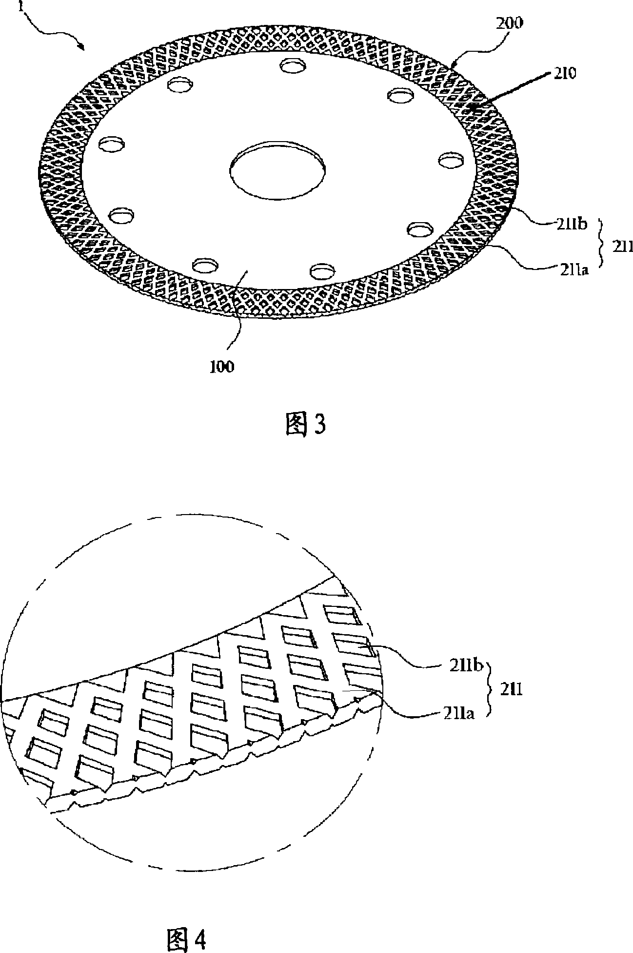
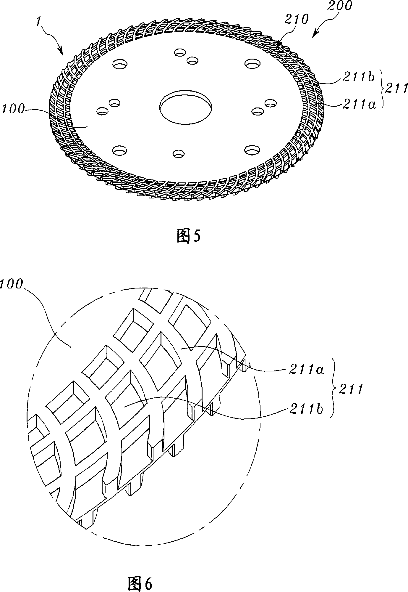
[0058] [55] FIG. 3 is a perspective view of a circular saw blade with a cutting tip according to one embodiment of the present invention, FIG. 4 is an enlarged view of the cutting tip shown in FIG. 3 , and FIG. 5 is a circular saw blade with a cutting tip according to another embodiment of the present invention. A perspective view of a circular saw blade, Figure 6 is an enlarged view of the cutting tip shown in Figure 5, and Figure 7 is a cavity formed in the cutting tip when the circular saw blade shown in Figure 3 and Figure 5 is used for the cutting process schematic diagram.

[0059] [56] FIGS. 3 to 6 show a circular saw blade 1 for cutting an object such as ferrite material, stone material, metal material or ceramic tile. Referring to FIGS. 3 to 6 , the circular saw blade 1 incl...


PUM

PropertyMeasurementUnit
widthaaaaaaaaaa
particle sizeaaaaaaaaaa
widthaaaaaaaaaa

Abstract

Disclosed is a saw blade capable of rapid cutting for various objects, such as jewelry, ferrite materials, stone, metallic materials, or ceramic tiles. The shape of the saw blade is modified such that performance and life time of the saw blade are improved. And also the manufacturing process for the saw blade is simplified, thereby reducing the manufacturing cost for the saw blade. The cutting tip is formed at upper and lower surfaces thereof with a mesh pattern, thereby enhancing the cutting performance by 30% as compared with that of a conventional cutting tip. The cutting tip represents superior cooling efficiency so that body of the saw blade is not broken during the cutting process, thereby ensuring safety of a worker and expanding the life time of the saw blade. The life time of the cutting tip is controlled by adjusting the content of diamond powder contained in the segment on the basis of hardness of a metal bond, regardless of the chemical composition and composition ratio of the metal bond contained in the segment. The cutting tip is suitable for various objects to be cut and the saw blade having the cutting tip is easily fabricated according to applications thereof, so that the manufacturing process for the saw bladeis simplified and the manufacturing cost for the saw blade is significantly reduced.

Description

technical field [0001] [1] The present invention relates to a saw blade capable of rapidly cutting various objects such as jewelry, ferrite material, stone material, metal material or ceramic tile. More particularly, the present invention relates to a cutting tip structure and a saw blade including such a tip. The shape of the cutting tip and saw blade has been improved, which can improve the cutting performance and service life of the saw blade. In addition, the manufacturing process of the saw blade can be simplified, and the manufacturing cost of the saw blade can also be reduced. Background technique [0002] [2] It is well known in the art that a saw is equipped with a plurality of teeth arranged in series to cut various materials such as wood, synthetic resin or metal. Depending on how the saw is operated, saws are divided into automatic saws and manual saws. Manual saws operate at low speeds and are primarily used to cut materials with relatively low hardness, so t...

Claims


Application Information

Patent Timeline
Patent Type & Authority Applications(China)
IPC IPC(8): B23D61/02B23D61/00
CPCB24D7/18B24D5/12B28D1/121
Inventor 曹昶臣
Owner 曹昶臣
Why Eureka
Try Eureka