Ground drilling hammer and the driving method

A drilling and hammer technology, which is used in the field of drilling hammers and drives for excavation, can solve the problems such as the compressed air function is not effectively performed, the drilling equipment is not easy to repair and maintain, and it is broken or damaged.

Inactive Publication Date: 2008-03-19
EVERDIGM ROCK TOOLS CORP
View PDF2 Cites 5 Cited by
  • Summary
  • Abstract
  • Description
  • Claims
  • Application Information

AI Technical Summary

Problems solved by technology

However, this patent also has some disadvantages, the supply of pressurized air is carried out only through the opening of the central channel of the piston and the outlet of the intake pipe, so that the function of the compressed air for the ascent and descent, such as the ascent and descent movement of the piston, is not are effectively implemented, and because the arithmetic ratio of resistance and density of the components is applied to the hammer, the hammer

Method used


Image

  • Ground drilling hammer and the driving method
  • Ground drilling hammer and the driving method
  • Ground drilling hammer and the driving method

Examples


no. 1 example

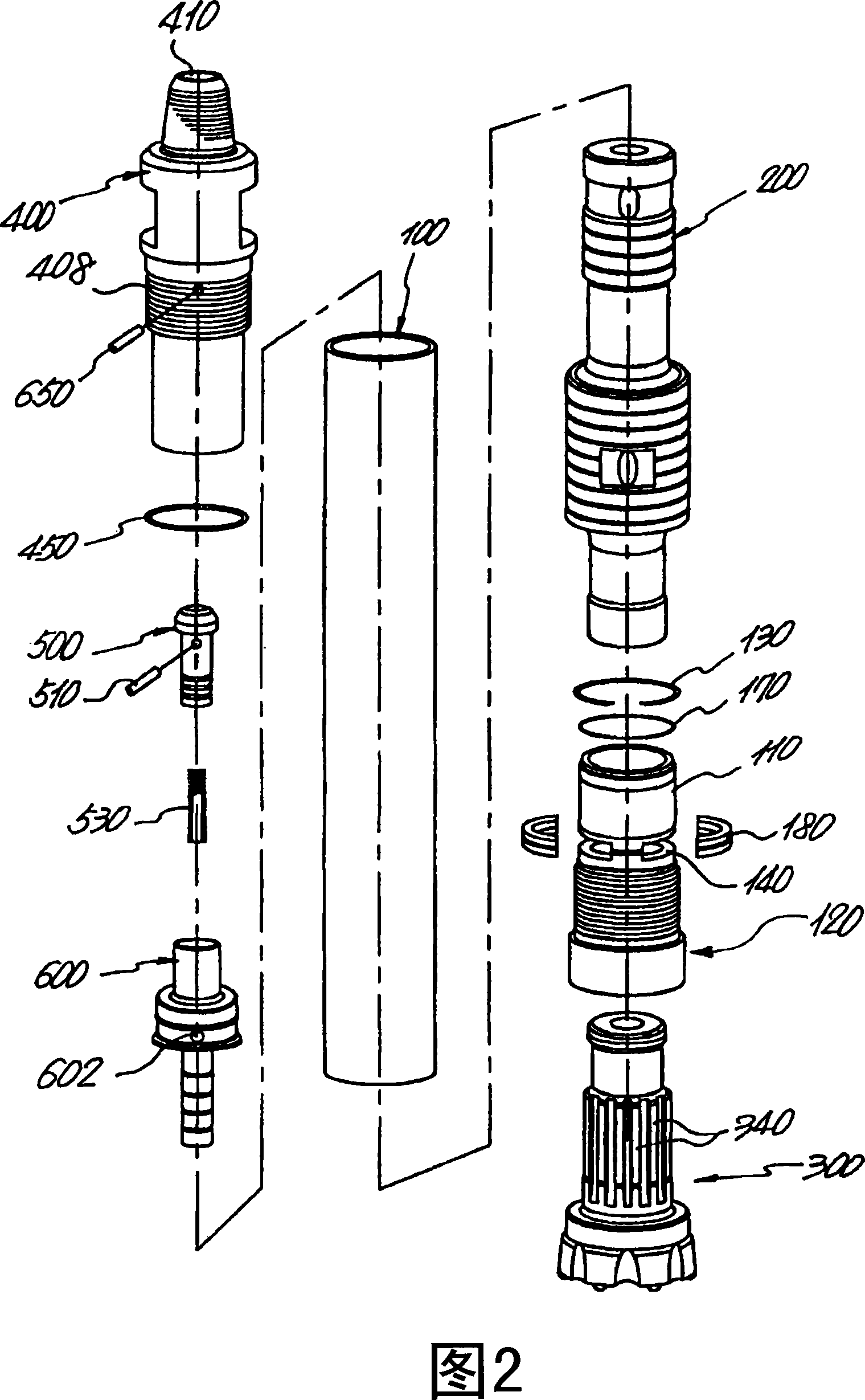
[0036] Fig. 2 is an exploded perspective view of the pneumatic hammer for rock drilling in an assembled state according to the first embodiment of the present invention.

[0037] With reference to Fig. 2, have shown the rear hammer head 400 that is suitable for being installed on the inner circumference of the upper end of piston sleeve 100, O type ring 450, check valve 500, pin 510, the inner hole that is suitable for being installed in check valve 500 The coil spring 530 of 520, and the guide body 600 having the stop hole 602 formed in its outer peripheral surface, are disassembled in this order. In this example, the piston 200 and the chuck 120 are mounted to the lower end of the piston casing 100, and it is shown that the hammer head 300 performs drilling work due to collision with the piston 200. Referring to FIG. Reference numerals are not explained in FIG. 2 , reference numeral 110 designates a bushing, 130 designates a stop ring, reference numeral 140 designates a hamm...


PUM


Abstract

Disclosed herein is a pneumatic operated hammer for rock drilling, the hammer comprising a cylindrical casing, a back head mounted at an upper portion of the casing, a check valve for opening/closing a compressed air passageway in the casing, a guide for supporting the check valve, a piston adapted to ascend and descend with compressed air in the casing, and a button bit for performing a drilling work through the striking of the piston. The piston is extended to a certain length to conform to the work condition of the pneumatic hammer to thereby prevent a water back-flow phenomenon in which underground water, etc., is introduced into the drilling equipment during the drilling work, compressed air passageways and variable compressed air chambers are formed between the piston and the casing so that when the piston ascends by the compressed air, it abruptly ascends at a load-free state, and the piston has axial portions with a reference diameter and different outer diameters so that it is possible to manufacture a hammer bit having a plurality of variable compressed air chambers formed between the casing the piston to fit for the work capacity. The piston ascended in a load-free state strikes the button bit with its rapid and strong striking force produced by the compressed air supplied from the variable chambers while abruptly descending to thereby perform the drilling work.

Description

technical field [0001] The present invention relates to a pneumatic hammer and a driving method thereof for rock drilling and drilling operations in formations and rocks, and more particularly, to a pneumatic drilling hammer and a driving method thereof in which some air passages are uniformly The intervals are concentrically arranged around the central axis of the back head (back head), and the compressed air required to drive the hammer is supplied in a central and distributed manner (a central and distributed manner), and the piston is extended to a certain length In order to meet the operating conditions of the pneumatic drill hammer, thus preventing water backflow phenomena, such as groundwater flowing into the drilling equipment during drilling operations, the outer diameters of the corresponding axial parts of the pistons are made different so as to be different between the piston and the piston sleeve. A variable air pressure chamber is formed between them, so that whe...

Claims


Application Information

Patent Timeline
IPC IPC(8): E21B1/30
CPCE21B4/14E21B10/38
Inventor 林秉德
Owner EVERDIGM ROCK TOOLS CORP
Why Eureka
Try Eureka