Substrate terminal cleaning apparatus and substrate terminal cleaning method

A cleaning device and cleaning technology, which are applied to the cleaning method using tools, the cleaning method using liquid, the cleaning method and the utensils, etc., can solve the problems of the elongation of stains, hinder the quality improvement and enlargement of the liquid crystal panel, etc., and achieve high precision Effect of cleaning action

Active Publication Date: 2008-03-26
PANASONIC CORP
View PDF2 Cites 6 Cited by
  • Summary
  • Abstract
  • Description
  • Claims
  • Application Information

AI Technical Summary

Problems solved by technology

However, in the structure of the existing cleaning device as described above, from the beginning to the end of the wiping cleaning of the terminal portion, the same portion of the cleaning cloth is in contact with the terminal portion, and there is an increase in the cleaning area due to the terminal portion. When the dirt that was wiped off once is stretched and reattached from the cleani

Method used


Image

  • Substrate terminal cleaning apparatus and substrate terminal cleaning method
  • Substrate terminal cleaning apparatus and substrate terminal cleaning method
  • Substrate terminal cleaning apparatus and substrate terminal cleaning method

Examples


no. 1 approach

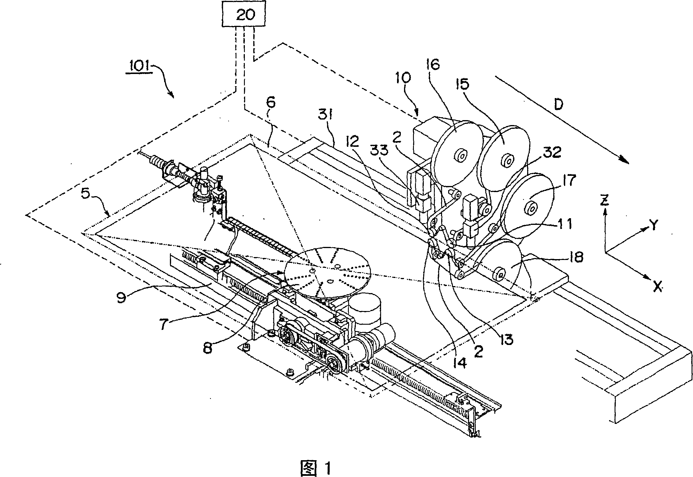
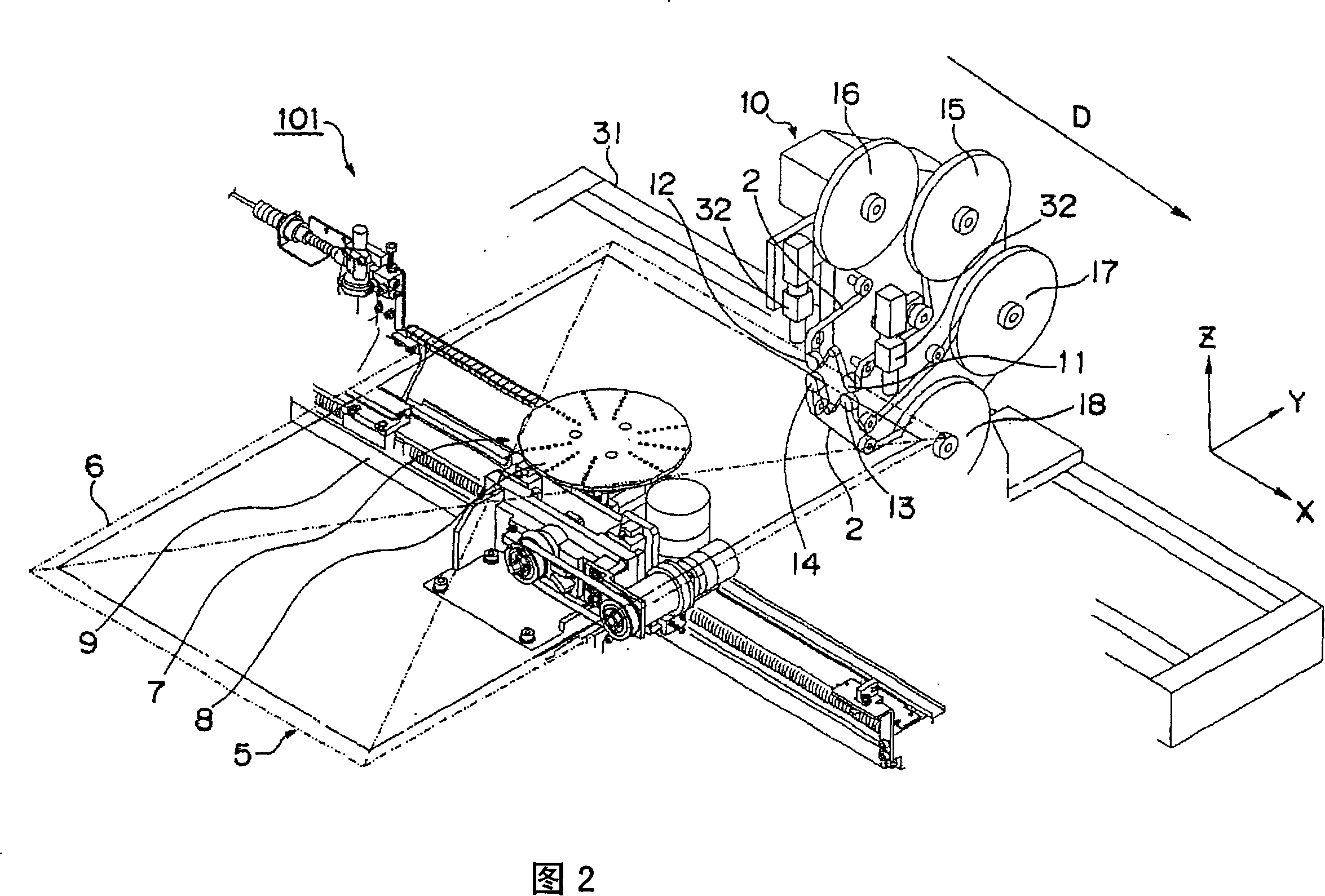
[0060] FIG. 1 is a schematic perspective view showing a main configuration of a terminal cleaning device 101 as an example of a substrate terminal cleaning device according to a first embodiment of the present invention. The terminal cleaning device 101 according to the first embodiment is made by contacting a cleaning cloth as an example of a cleaning member with an edge or the like on the surface of a substrate for a flat display panel such as a liquid crystal display device (liquid crystal panel) or a plasma display panel (PDP). A device for cleaning by contacting and wiping the terminal part (or the surface of the terminal part or the area where the terminal part is arranged) formed at the terminal. In addition, in this specification, the so-called "cleaning" refers to removing stains adhering to the object by washing or sweeping, including, for example, wet cleaning using a cleaning cloth soaked in an organic solvent or the like, or cleaning without using a solvent. Two t...

no. 2 approach

[0114] In addition, this invention is not limited to the said embodiment, It can implement in other various forms. For example, FIG. 10 is a schematic explanatory diagram showing a partial structure of a cleaning unit 110 included in a terminal cleaning device according to a second embodiment of the present invention.

[0115] As shown in FIG. 10 , in the cleaning unit 110, there is a twisting mechanism 120 that reverses the front and back of the cleaning cloth 2 so that the cleaning cloth 2 that is in contact with the terminal portion 6 of the substrate 5 by the first cleaning head 111 The abutting surface and the abutting surface of the cleaning cloth 2 abutting against the terminal portion 6 by the second cleaning head 112 are reversed from each other, and have a different structure from the cleaning unit 10 of the first embodiment in this point. .

[0116] Specifically, as shown in FIG. 10 , the constituent parts of the cleaning unit 110 on the upper side have: four rolle...


PUM


Abstract

A substrate terminal cleaning apparatus which performs cleaning of a terminal section of a substrate by having a cleaning member abut to the terminal section. The substrate terminal cleaning apparatus is provided with a first supporting section for supporting the cleaning member at a first position; a second supporting section for supporting the cleaning member at a second position; a cleaning head section for applying pressure to a part of the cleaning member, which is being supported between the first position and the second position, by having the part of the cleaning member abut to the terminal section of the substrate; a supporting section moving apparatus for integrally moving the first supporting section and the second supporting section in a direction along the terminal section; and a cleaning head moving apparatus for moving the cleaning head section in the direction along the terminal section, at a second moving speed different from a first moving speed at which the supporting section moving apparatus moves the first supporting section and the second supporting section.

Description

technical field [0001] The present invention relates to a substrate terminal cleaning device for cleaning a terminal portion on a substrate, and more particularly to a liquid crystal panel mounting terminal surface for improving the mounting quality of ICs and the like mounted on the mounting terminal surface of a liquid crystal panel serving as the substrate. A cleaned liquid crystal panel terminal cleaning device and a substrate terminal cleaning method. Background technique [0002] In recent years, the demand for liquid crystal panels has increased rapidly, and there is a strong desire to improve the quality and yield of liquid crystal panels. Among them, in order to improve the quality and yield in the liquid crystal panel mounting process, it is effective to clean (clean or sweep) the mounting surface again before the mounting process, and interest in liquid crystal panel terminal cleaning devices has increased. [0003] Here, the structure (for example, refer patent ...

Claims


Application Information

Patent Timeline
IPC IPC(8): B08B7/04B08B1/02B08B3/04G02F1/13G02F1/1345G09F9/00
CPCG02F1/13458G02F2001/1316G02F1/1303B08B1/008G02F1/1316H01L21/304
Inventor 渡边雅也辻慎治郎藤原启二片野良一郎
Owner PANASONIC CORP
Why Eureka
Try Eureka