Method of controlling a hydrostatic drive

A drive and hydrostatic technology, applied in the direction of brakes, brake components, control devices, etc., to achieve the effect of torque increase

Inactive Publication Date: 2008-03-26
BOSCH REXROTH AG
View PDF0 Cites 13 Cited by
  • Summary
  • Abstract
  • Description
  • Claims
  • Application Information

AI Technical Summary

Problems solved by technology

[0005] A disadvantage of the known drive is that, in order to remove the pressure medium, the hydraulic engine is loaded with pressure medium directly from the high-pressure reservoir

Method used


Image

  • Method of controlling a hydrostatic drive
  • Method of controlling a hydrostatic drive
  • Method of controlling a hydrostatic drive

Examples


Embodiment Construction

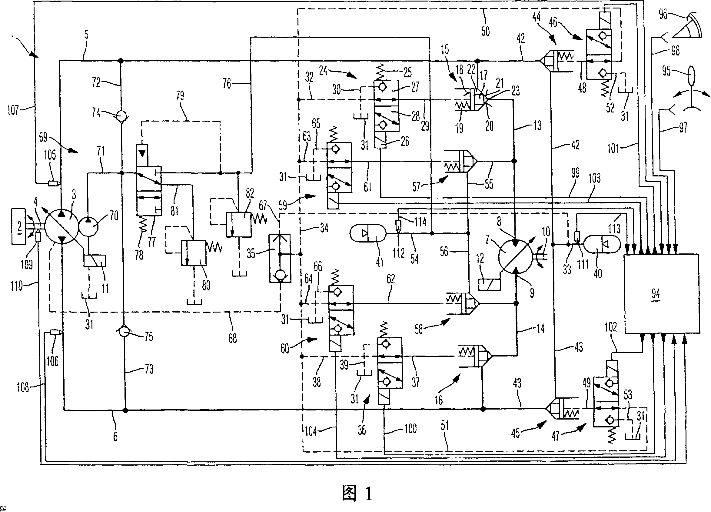
[0028] FIG. 1 shows a schematic view of a hydrostatic drive 1 according to the invention. Said hydrostatic drive 1 according to the invention may for example be a traction type drive in a utility vehicle. However, the invention is not limited to traction drives. Conversely, all drives with hydrostatic transmission can be manufactured with the design according to the invention.

[0029] The hydrostatic drive 1 comprises a drive engine 2 . The drive engine 2 drives a hydraulic pump 3 through a drive shaft 4 . The hydraulic pump 3 is an adjustable hydrostatic piston mechanism that can be designed for bi-directional transmission. The hydraulic pump 3 can be delivered into the first working line 5 or the second working line 6 according to the set delivery direction. A hydraulic engine 7 is connectable to the first working line 5 and the second working line 6 . The hydraulic engine 7 has a first working line connection 8 and a second working line connection 9 . The first worki...


PUM


Abstract

The present invention relates to a method for controlling the hydrostatic driver (1). The hydrostatic driver (1) includes a hydraulic pump (3) and a hydraulic engine (7). The hydrostatic driver (1) also includes a first and a second container (40 and 41) which are used for storing and restoring energy. The pressure energy is stored in the first container (40). The first container (40) is connected to the suction side of the hydraulic pump (3) in order to restore the pressure energy in the first container (40). The working line (8 and 9) of the hydraulic engine (7) is connected to the second container (41). Besides, the downstream working line connecting parts (9 and 8) of the hydraulic engine (7) are disconnected with the suction side of the hydraulic pump (3).

Description

technical field [0001] The present invention relates to a method of controlling a hydrostatic drive recoverable from stored energy. Background technique [0002] Hydrostatic drives are often used to drive utility vehicles. In such a connection, part of the kinetic energy can be stored by the hydrostatic drive during the braking operation and can subsequently be recovered. In AT 395 960B the use of a hydrostatic drive in a closed circuit with a hydraulic pump intended to achieve the technical effect of transmission in one direction only is proposed. A working line on the delivery side is connected to the high pressure reservoir, which working line connects the hydraulic pump to the hydraulic engine. A second reservoir is also provided, which is constructed as a low-pressure reservoir and is connected to the working line on the suction side relative to the hydraulic pump. The high-pressure reservoir and the low-pressure reservoir are respectively permanently connected to th...

Claims


Application Information

Patent Timeline
Patent Type & Authority Applications(China)
IPC IPC(8): F15B21/14F15B1/02B60T1/10B60K6/12F16H61/40F16H61/4017F16H61/4096F16H61/4157F16H61/42
CPCB60T1/10F16H61/4017F15B2211/6313F15B2211/7058F15B2211/6653F16H61/4157F16H61/42F15B2211/6309F15B1/024F15B2211/6333F15B2211/6652F15B21/14B60K6/12B60K17/10F15B2211/88F15B2211/20561F15B2211/212Y02T10/6208F16H61/4096Y02T10/62
Inventor 马蒂亚斯·穆勒彼得·施穆特迈尔
Owner BOSCH REXROTH AG
Why Eureka
Try Eureka