Anisotropic electrically conductive structure

一种导电结构、各向异性的技术,应用在绝缘载体上的导电层、导电材料、导电材料等方向,达到实现连接的效果

Inactive Publication Date: 2008-03-26
3M INNOVATIVE PROPERTIES CO
View PDF0 Cites 7 Cited by
  • Summary
  • Abstract
  • Description
  • Claims
  • Application Information

AI Technical Summary

Problems solved by technology

However, it is not always easy to maintain insulation between conductive paths as these materials soften and may fluidize when connected

Method used


Image

  • Anisotropic electrically conductive structure
  • Anisotropic electrically conductive structure

Examples


Embodiment Construction

[0015] The present invention will be described below with reference to examples. It should be understood that the present invention is by no means limited to these Examples.

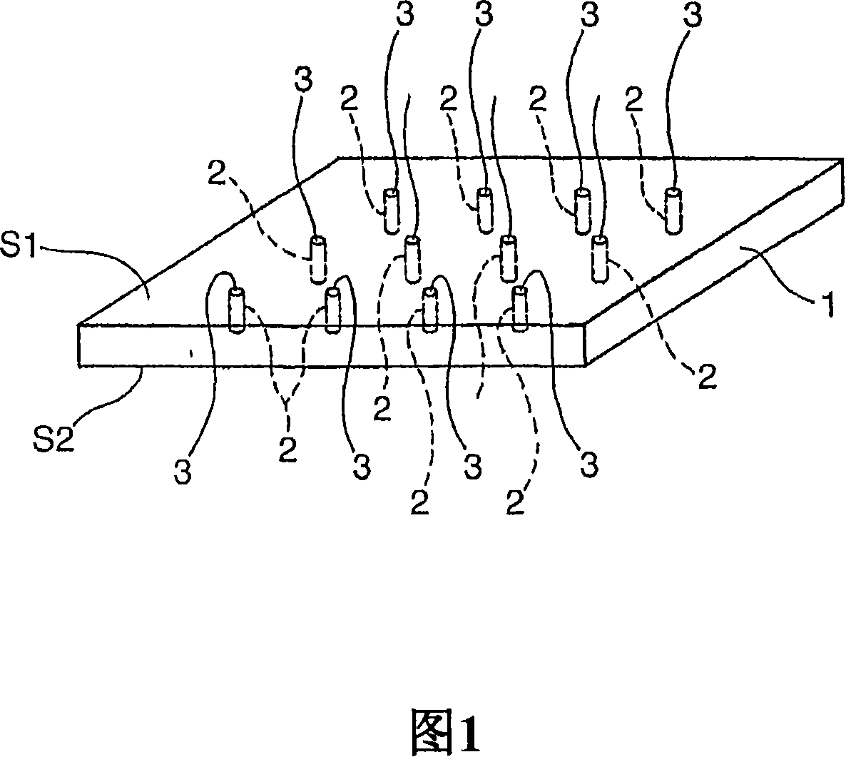
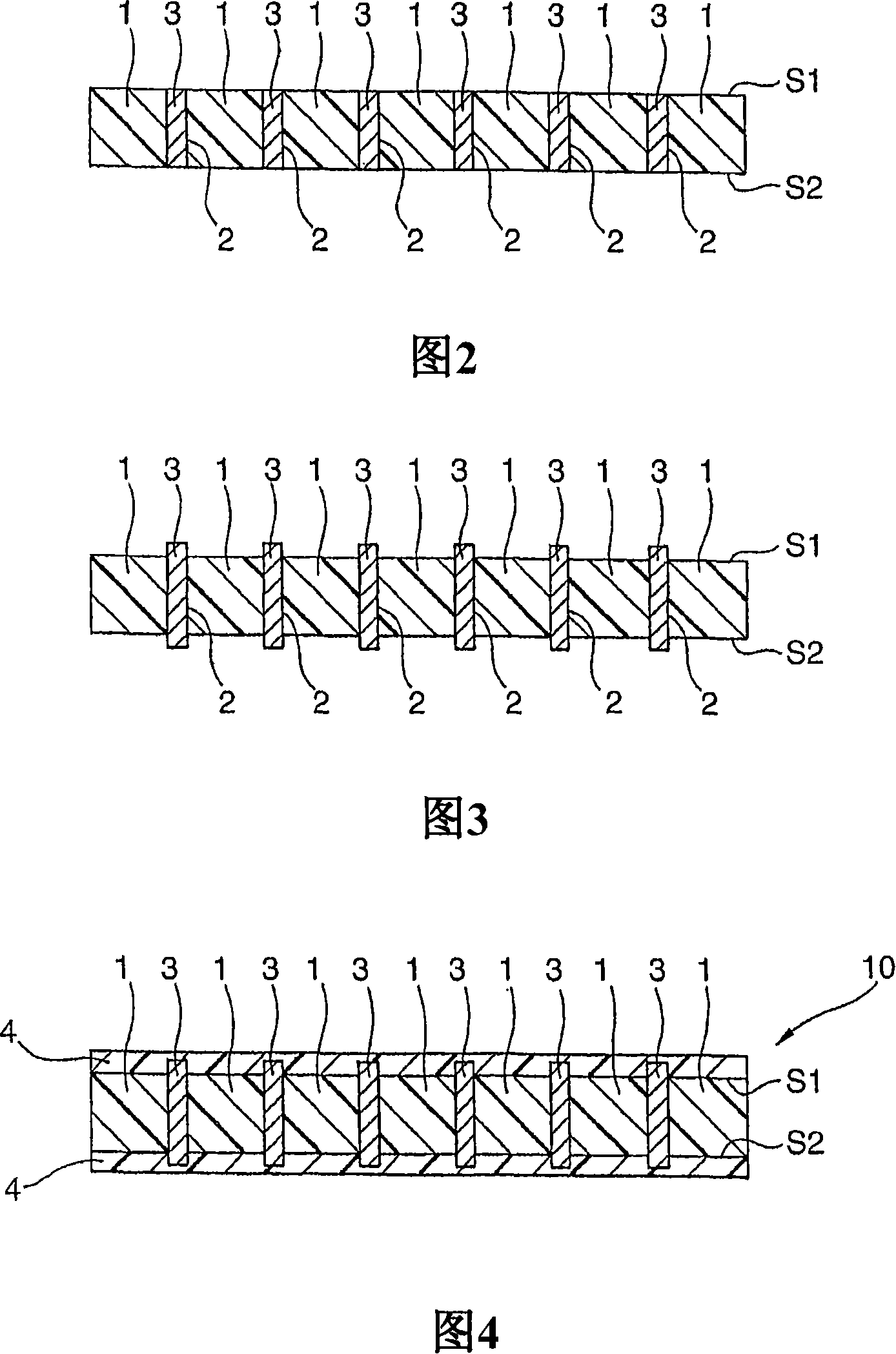
[0016] The anisotropic conductive structure includes: a dielectric substrate having a first surface and a second surface; a thermally cured adhesive layer disposed on at least one or both of the first plane and the second plane; at least from a plurality of channels extending from the first surface of the substrate to the second surface; and a conductive member in the channels; wherein, at a temperature required to thermally cure the heat-curable adhesive layer, The dielectric matrix does not exhibit thermal fluidization.

[0017] 1 and 2 are perspective and cross-sectional views, respectively, showing an embodiment of a structure including conductive members in a plurality of channels extending from a first surface to a second surface of a dielectric substrate. As shown, the conductive members 3 are c...


PUM

PropertyMeasurementUnit
cure temperatureaaaaaaaaaa

Abstract

An anisotropic electrically conductive structure comprising: a dielectric matrix having a first surface and a second surface; a heat curable adhesive layer disposed on at least one or both of said first surface and said second surface; a plurality of passages at least extending from said first surface of said matrix to said second surface of said matrix; and electrically conductive members in said passages; wherein said dielectric matrix does not exhibit thermal fluidization at a temperature required for heat curing of said heat curable adhesive layer.

Description

technical field [0001] The invention relates to an anisotropic conductive structure. Background technique [0002] Precision electronic components, such as integrated circuit chips or devices, terminal pads of printed circuit boards, liquid crystal displays, etc., have electrical connection parts for connection with external circuits. In the case of connecting a chip to an external circuit, in particular, these electrical connection parts exist in high density, and the pitch of each of these electrical connection parts from an adjacent part is generally 0.1 mm or less. These high-density electrical connection parts must be electrically insulated from adjacent parts in order to avoid short circuits between them. Therefore, anisotropic conductive structures that conduct electricity in only one direction and are electrically insulating in the other direction have been commonly used in these connection components. [0003] There are various known documents on anisotropic condu...

Claims


Application Information

Patent Timeline
Patent Type & Authority Applications(China)
IPC IPC(8): H01L23/498
CPCH01L24/29H05K2201/10424H01L2924/01002H01L23/49894H01L2924/01074H01L2924/0781H01L2924/01027H01L2924/01047H05K2201/10378H01L24/83H01L2924/0105H01L2924/01029H01L2224/2919H01L2224/83101H01L2924/01033H01L2924/01082H01L2924/01046H01L2924/01049H01L2224/838H01L2924/01079H01L2924/01015H01L23/49827H01L2924/0665H01L2924/01006H01L2924/01078H05K3/323H01L2924/14H01L2924/00H01B1/00H01B5/14
Inventor 岛田正志
Owner 3M INNOVATIVE PROPERTIES CO
Why Eureka
Try Eureka