
Electronic sphygmomanometer for medical purpose

An electronic sphygmomanometer, electronic technology, applied in the measurement of pulse rate/heart rate, cardiac catheterization, etc., can solve the problems of pollution, "mercury pollution, cannot be used as clinical diagnosis basis, etc., and achieve the effect of solving mercury pollution and strong practicability

Inactive Publication Date: 2008-04-02
辛学刚 +1
View PDF0 Cites 11 Cited by
  • Summary
  • Abstract
  • Description
  • Claims
  • Application Information

AI Technical Summary

Problems solved by technology

[0004] In order to overcome the "mercury pollution" brought by the traditional mercury sphygmomanometer and the current electronic sphygmomanometer measurement results cannot be used as the basis for clinical diagnosis. A medical electronic sphygmomanometer with exactly the same measurement principle as the "mercury sphygmomanometer"
This medical electronic sphygmomanometer (hereinafter referred to as "the present invention") provided by the present invention replaces the traditional "mercury" by using electronic pressure measurement technology, and solves the problem of "mercury pollution"; The same Korotkoff sound method measurement principle, after measurement calibration, its measurement results can be used as a basis for clinical diagnosis, which overcomes the deficiency of "the measurement results of electronic sphygmomanometers using the principle of oscillometric method cannot be used as clinical medical basis"

Method used


Image

  • Electronic sphygmomanometer for medical purpose
  • Electronic sphygmomanometer for medical purpose
  • Electronic sphygmomanometer for medical purpose

Examples


Embodiment Construction

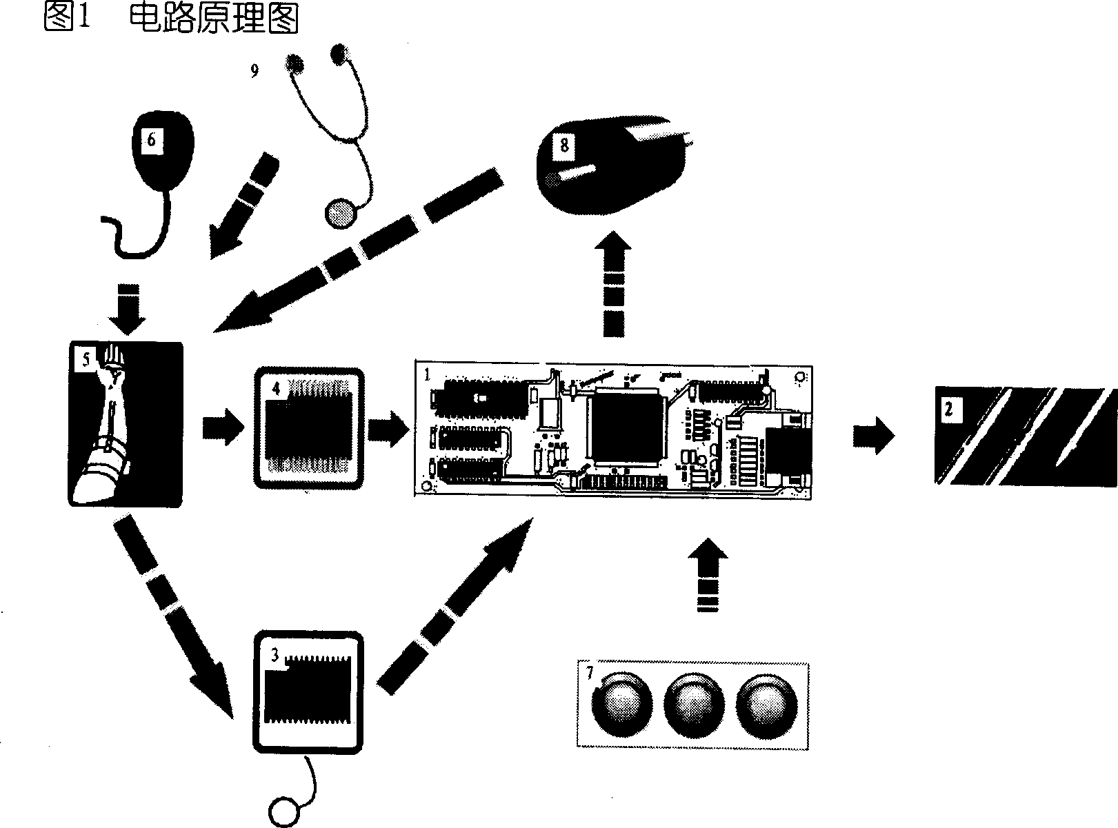
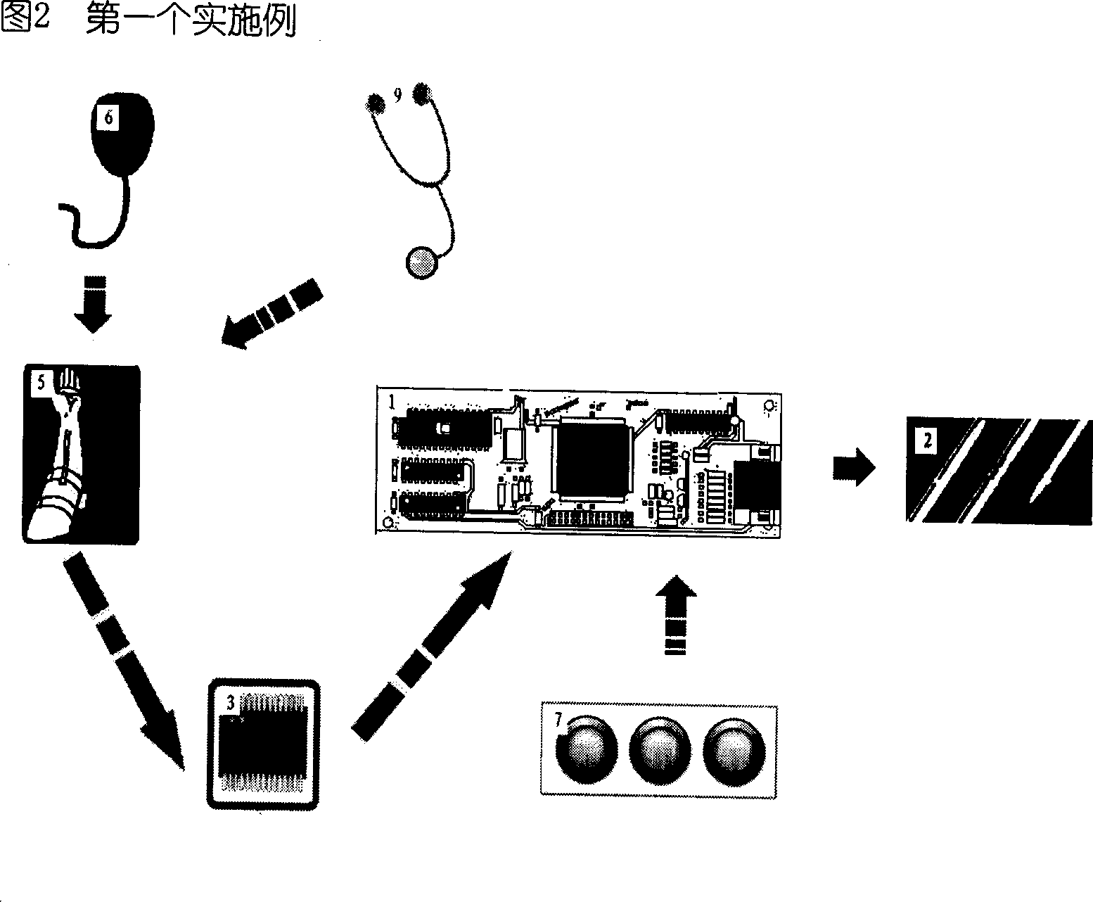
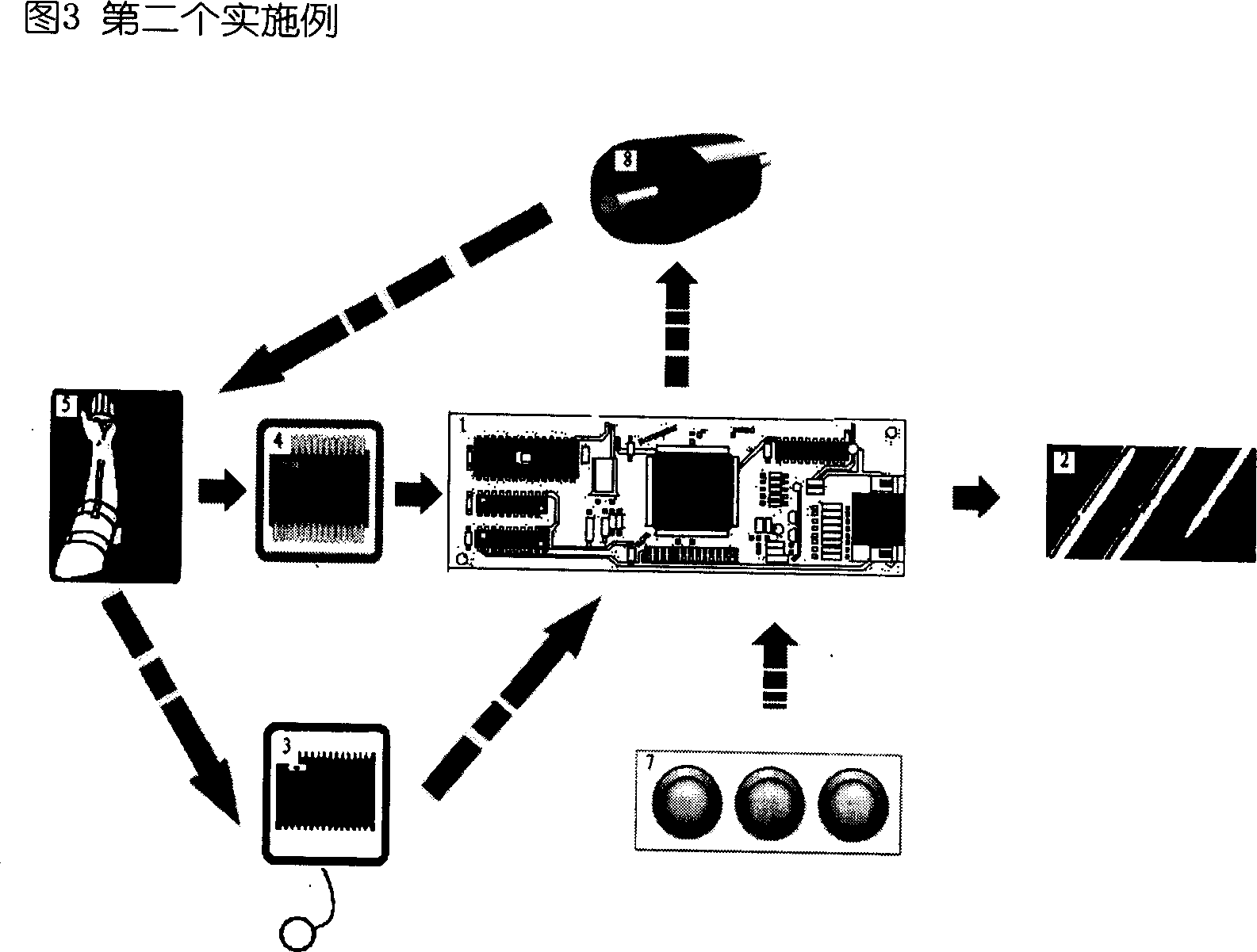
[0012] In Fig. 1, the single-chip system board (1) is the control core of the whole sphygmomanometer, the pressure sensor (4) senses the inflation pressure in the cuff inflation device (5), and the pulse sound sensor (3) senses the pulse of the radial artery. The vibration sound, the pressure sensor (4) and the pulse sound sensor (3) send the sensed parameters to the single-chip system board (1) for measurement, and the single-chip system board (1) displays the measurement results through the liquid crystal display device (2) . There are two working modes for inflating the cuff inflation device (5), which are completed by using the manual inflation ball (6) or the inflation motor unit (8) respectively. The single-chip system board (1) directly accepts the key information input by the key matrix (7), and executes corresponding actions. The keys of the key matrix (7) include a start measurement key, a data format conversion key, and the like. After the measurement preparations...


PUM


Abstract

A medical electronic sphygmomanometer using an electronic circuit to examine pressure and pulse sound, measures a blood pressure on the basis of a Korotkoff sound theory. The electronic sphygmomanometer solves the problems of the existing Korotkoff sound method that must use mercury for measuring blood pressure. The operational principle can be seen in the attached drawing. The attached drawing: 1: a single chip system board; 2: a liquid crystal display device; 3: a pulse sound sensor; 4: a pressure sensor; 5: a cuff air charging device; 6: a manual air charging ball; 7: a keypad matrix; 8: an air charging motor unit; 9: a standard medical stethoscope. The pressure sensor (4) is for sensing the pressure in the cuff air charging device (5); the pulse sound sensor is for sensing the pulse sound; the single chip system board (1) receives sensor data and displays results through the liquid crystal display device. The manual air charging ball (6) or the air charging motor unit (8) can be used for charging air to the cuff air charging device (5). The blood pressure can be measured according to the Korotkoff sound method. The standard medical stethoscope (9) can replace the pulse sound sensor (3), and the blood pressure can be measured by human.

Description

Technical field [0001] The invention relates to a medical non-invasive electronic device for measuring blood pressure in vitro, which is an electronic blood pressure monitor capable of accurately measuring systolic and diastolic blood pressure of a measured object based on the Korotkoff sound principle. Background technique [0002] At present, the sphygmomanometers commonly used in clinic to measure blood pressure are mainly mercury sphygmomanometers. Mercury sphygmomanometers measure blood pressure based on the Korotkoff sound principle. During the measurement, the measurer uses a stethoscope to listen to the beating sound of the pulse, so as to judge the blood pressure of the measured object. The specific method is: the measurer first inflates the cuff and increases the air pressure in the cuff until the cuff compresses the blood vessel and the pulse sound disappears completely. Then deflate the cuff slowly. The mercury column pressure of the cuff when the first pulse b...

Claims


Application Information

Patent Timeline
IPC IPC(8): A61B5/0225A61B5/024
Inventor 辛学刚
Owner 辛学刚
Learn More