Malfunction detection system and method thereof

A technology for fault detection and line faults, applied in the direction of error detection/correction, measuring electricity, measuring devices, etc., can solve problems such as abnormal switch board key combination functions, increased detection costs, excessive tin, etc., to achieve the best industrial utilization value and increase Difficulty, the effect of reducing the cost of detection

Inactive Publication Date: 2010-09-22
INVENTEC CORP
View PDF5 Cites 0 Cited by
  • Summary
  • Abstract
  • Description
  • Claims
  • Application Information

AI Technical Summary

Problems solved by technology

[0004] Through the above detection method, it is possible to quickly detect whether any key unit on the switch board has an open circuit fault. Technology; SMT) when making boards, sometimes due to the operator's mistake, excessive tin will be caused when the pins of the key unit are welded to the corresponding contacts on the switch board, resulting in the pins of the key unit (especially the pins at the common end) Pins) and the grounded metal surface covering the key unit to protect the key unit are short-circuited, thereby causing the common end of the key unit to be grounded
Once the first interface (that is, the common terminal) of any key unit of the switch board is grounded, it will cause abnormal phenomena in the key combination function of the switch board, for example, when the operator only presses one of the key units of the switch board , it may cause another button unit (the operator did not activate the button unit) to be pressed at the same time (that is, the two button units are touched at the same time)
However, since the above-mentioned detection method is to ground the common end of the switch board in advance, it is impossible to detect whether there is a hidden danger in the common end of the switch board. It will cause the entire computer to run abnormally. At this time, the scope of fault detection is expanded to the entire computer, which not only increases the difficulty of fault detection, but also relatively increases the detection cost.

Method used


Image

  • Malfunction detection system and method thereof
  • Malfunction detection system and method thereof
  • Malfunction detection system and method thereof

Examples


no. 1 example

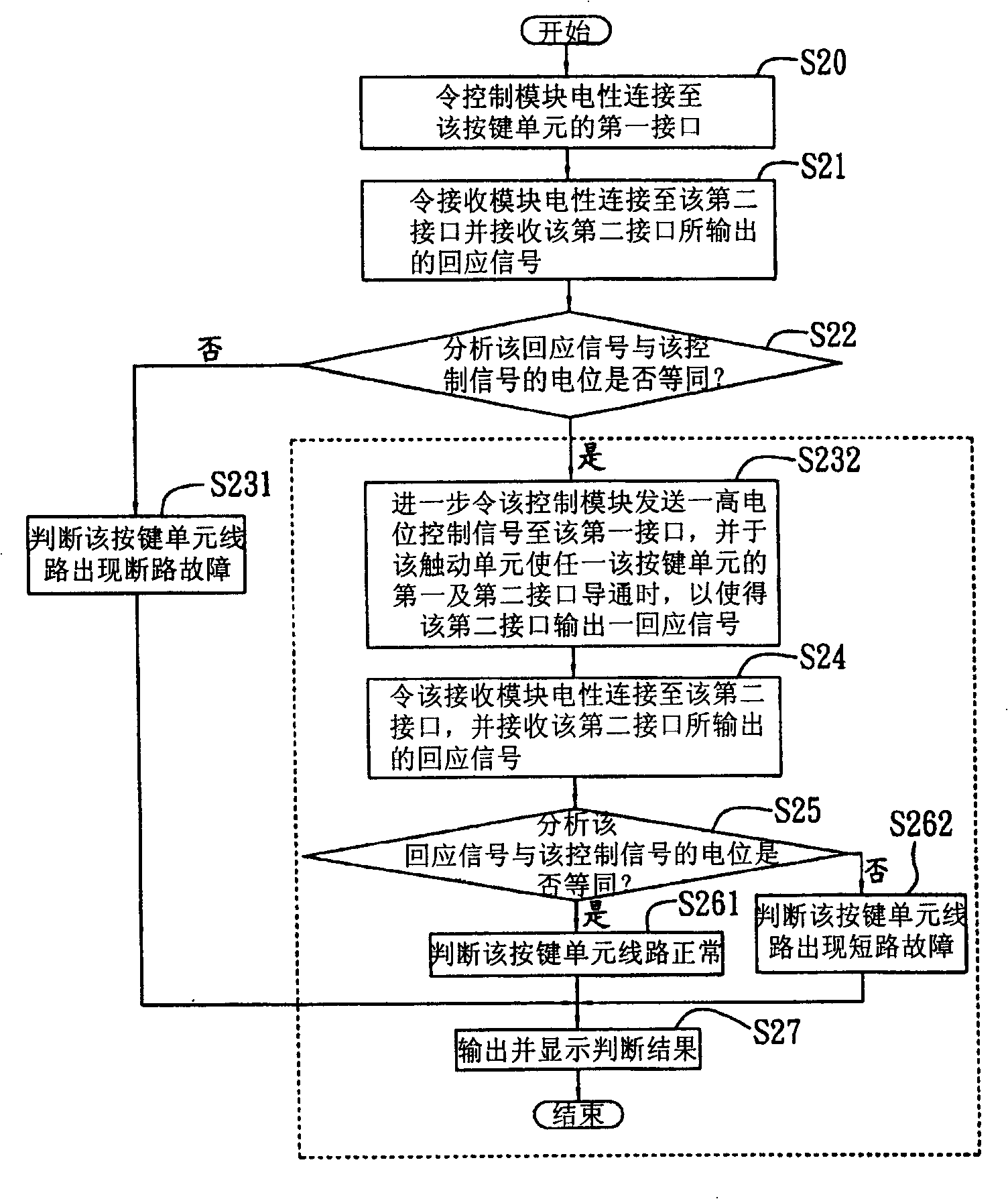
[0062] The difference between this embodiment and the preceding embodiments is that the fault detection method of the present invention is to make the control signal (in step S20) provided by the control module 11 for the first time be a low potential signal, and then according to the high potential signal sent by the control module 11 Signal control signal and the response signal received by the receiving module 14, when analyzing that the response signal is not equal to the control signal (that is, the response signal is a high potential signal at this time), determine the specific key switch 33 circuit of the key unit 3 Open circuit failure occurs (in step S231); when analyzing that the response signal is equal to the control signal (that is, the response signal is also a low potential signal at this moment), the control signal sent by the control module 11 is switched from low potential to The high potential signal is sent to the first interface 31 of the button unit 3 (in ...


PUM


Abstract

A fault detection system and method provides a test equipment connected with a key unit, wherein, the test equipment comprises a touch unit connected with the first interface and the second interface of the key unit. The method includes at least a first interface which realizes electric connection of a control module with the key unit, wherein, the control module transmits a control signal which controls the motion of the key unit to the first interface; moreover, the touch unit can realize electric conduction of the key unit with the corresponding first interface and the second interface so as to ensure that the corresponding second interface of the key unit outputs a back signaling; a receiving module is in electric connection with the second interface to receive the back signaling after the control module transmits the control signal; moreover, a processing module, according to the control signal transmitted by the control module and the back signaling received by the receiving module, analyzes whether the back signaling is identical to the control signal and makes judgment that the key unit has line fault when the back signaling is different from the control signal.

Description

technical field [0001] The invention relates to a fault detection technology, more specifically, to a fault detection system and method for detecting the line state of a multi-button unit on a circuit board. Background technique [0002] With the advancement of science and technology, computers have been widely used in different fields. Computers, especially notebook computers, are generally equipped with a switch board (switch board), and the switch board is provided with a multi-button unit to assist the operation of the notebook computer. Perform related operations such as power on / off, computer reset (reset), brightness adjustment, volume adjustment, etc. When an open circuit fault occurs on a key in the above key unit, it will affect the corresponding functions of the computer (such as failure to operate normally). Therefore, it is particularly important to carry out corresponding fault detection on the switch board before the switch board is shipped in large quantities...

Claims


Application Information

Patent Timeline
Patent Type & Authority Patents(China)
IPC IPC(8): G01R31/02G06F11/267
Inventor 吴长岭周皇村
Owner INVENTEC CORP
Why Eureka
Try Eureka