
Insulated-gate semiconductor device

An insulated gate type, semiconductor technology, applied in the direction of semiconductor devices, transistors, electric solid devices, etc., can solve the problems of narrowing the operating area, unable to configure transistor units, etc., and achieve the effect of ensuring the area of ​​the operating area

Inactive Publication Date: 2008-04-02
SANYO ELECTRIC CO LTD +1
View PDF1 Cites 4 Cited by
  • Summary
  • Abstract
  • Description
  • Claims
  • Application Information

AI Technical Summary

Problems solved by technology

Therefore, in the graphs of FIG. 12(A) and (B), part of the transistor cells near the gate pad electrode 48 cannot be arranged, and p + Type impurity region 49 control (design change) and the need to reduce the operating region (transistor cell layout area)

Method used


Image

  • Insulated-gate semiconductor device
  • Insulated-gate semiconductor device
  • Insulated-gate semiconductor device

Examples


no. 1 approach

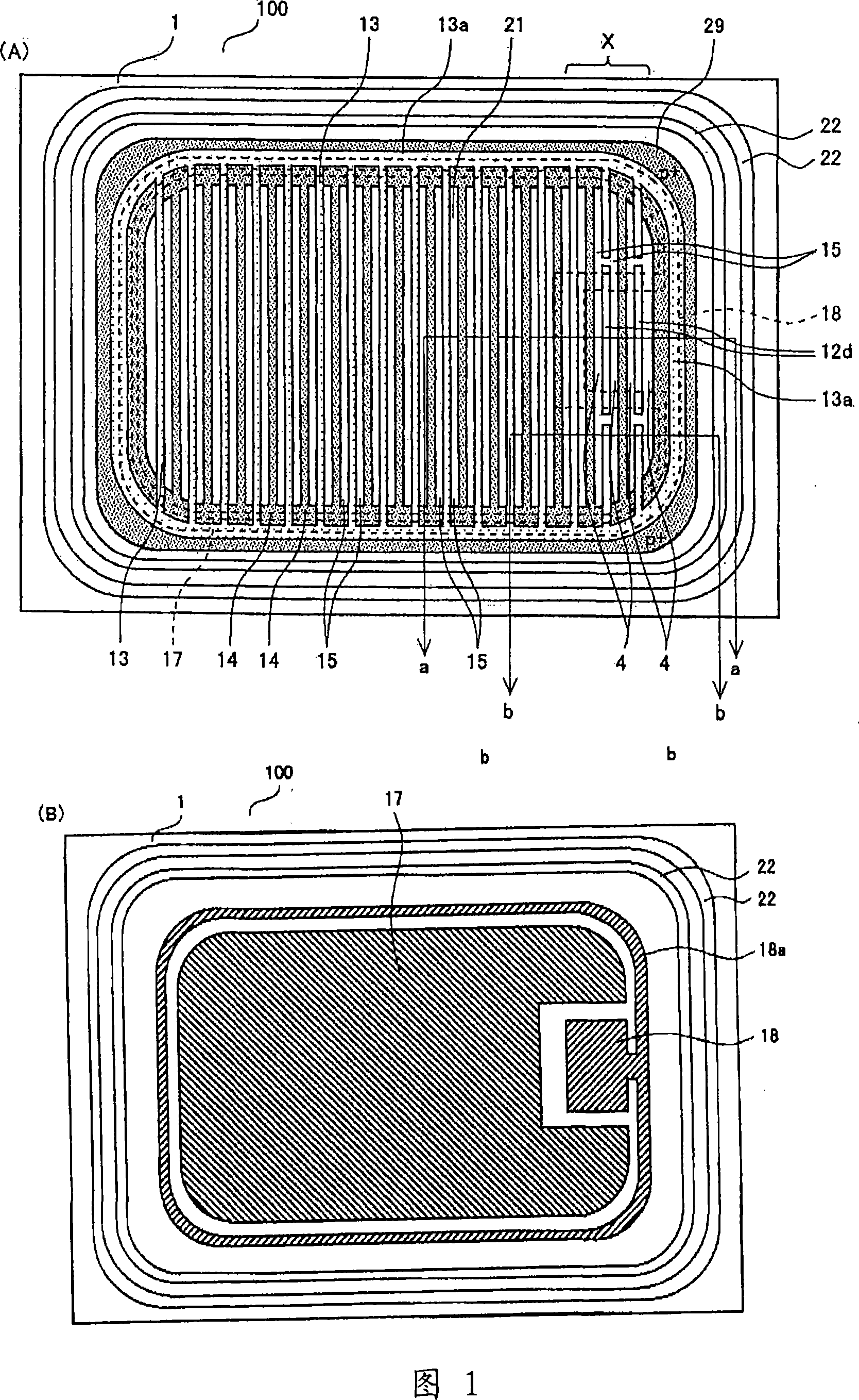
[0041] 1(A) and (B) are plan views of a MOSFET chip according to a first embodiment of the present invention. FIG. 1(A) is a plan view showing the metal electrode layer (source electrode, gate pad electrode, and gate wiring) with dotted lines omitting the interlayer insulating film, and FIG. 1(B) shows the source electrode, the gate pad electrode, and the gate wire. A floor plan of the graph of the wiring.

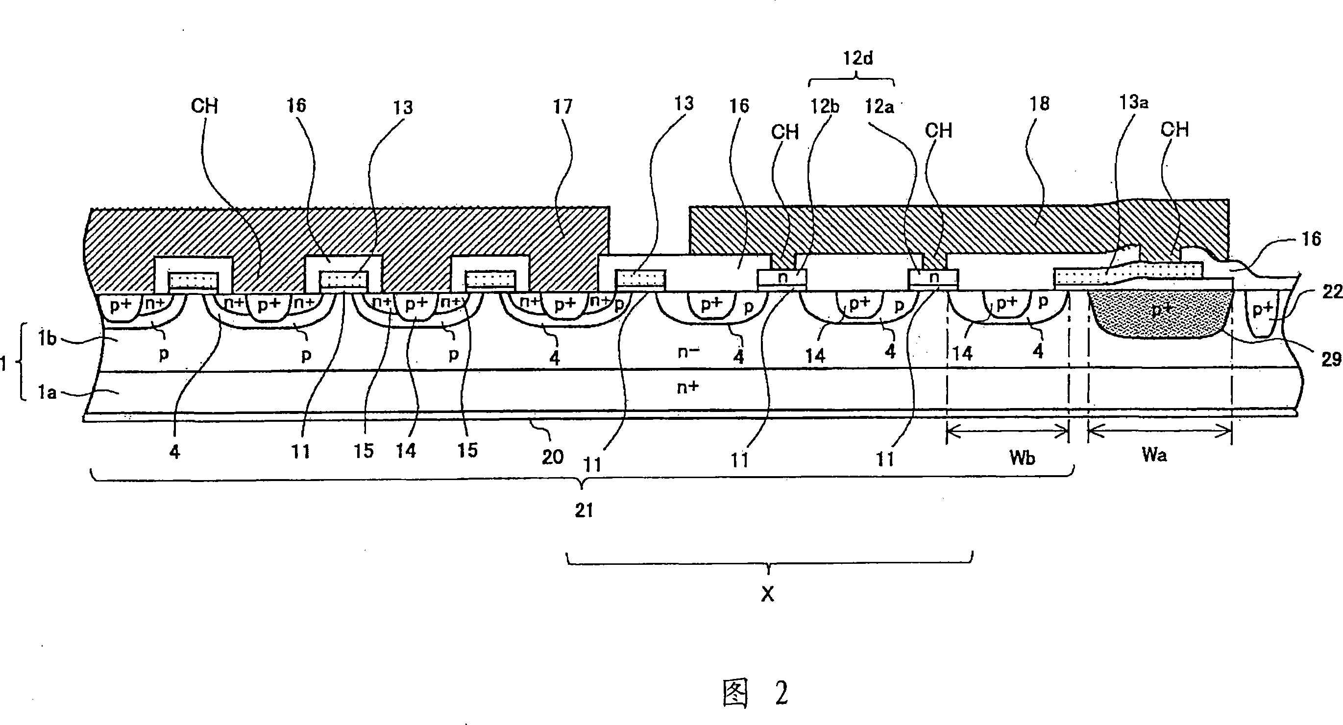
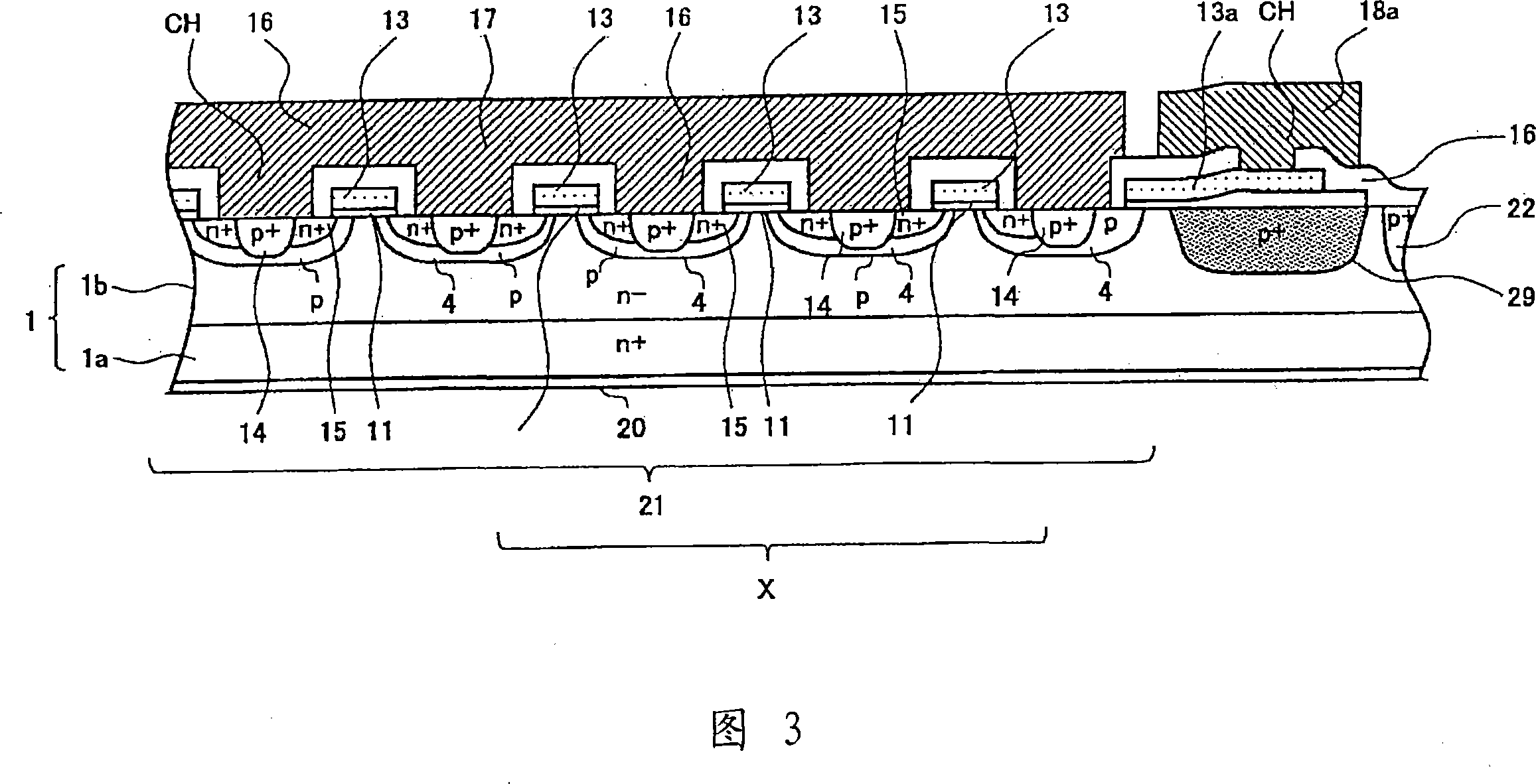
[0042] The MOSFET 100 of the present invention includes: an n-type semiconductor substrate 1, a channel region 4, a first insulating film 11, a gate electrode 13, a source region 15, a body region 14, a second insulating film 16, a gate pad electrode 18, and a source electrode 17. Protection diode 12d.

[0043] As shown in FIG. 1(A), gate electrodes 13 are provided in stripes on the surface of n-type semiconductor substrate 1 via a gate oxide film (not shown here) serving as a first insulating film. After the gate electrode 13 is deposited with polysilicon, impurities ar...


PUM


Abstract

The present invention relates to insulated-gate semiconductor device. Setting p<+> type impurity area below a gate pad electrode, the end portion of the p<+> type impurity area has sphere-shaped curvature. When the reverse breakdown voltage between drain-source electrodes reaches hundreds volts, an electric field at the sphere-shaped end portion will collect so that it can not obtain adequate drain-source reverse breakdown voltage. In a plane field, when augmenting the curvature of the angle portion of the p<+> type impurity area, it will lose the quantity of transistor unit configured in motion area. A channeling area connecting with the transistor unit is also configured below the gate pad electrode, and is fixed as source electric potential. Thus, a predetermined reverse breakdown voltage between a drain and a source is secured without forming a p+ type impurity region below the entire lower surface of the gate pad electrode. Furthermore, a protection diode is formed in polysilicon with a stripe shape below the gate pad electrode.

Description

technical field [0001] The present invention relates to an insulated gate type semiconductor device, and more particularly to an insulated gate type semiconductor device capable of sufficiently securing an operating region area and maintaining a high reverse withstand voltage. Background technique [0002] In a conventional insulated gate semiconductor device, a transistor cell is not disposed under a gate pad electrode (for example, refer to Patent Document 1). [0003] In addition, a plurality of protective diodes such as pn junctions may be connected in series under the gate pad electrode. In addition, in some cases, a diffusion region of high-concentration impurities is formed on the substrate below the gate pad electrode in order to ensure the reverse withstand voltage between the drain and the source. [0004] Figure 11 (A), (B) as a conventional insulated gate semiconductor device shows that a P + An example of an n-channel MOSFET with an impurity region. [0005] ...

Claims


Application Information

Patent Timeline
Patent Type & Authority Applications(China)
IPC IPC(8): H01L27/06H01L29/78
CPCH01L29/7813H01L29/7808H01L29/0619H01L27/0255H01L27/0629H01L29/7811H01L29/4238H01L2924/0002H01L2224/0603H01L2924/00
Inventor 野口康成小野寺荣男石田裕康
Owner SANYO ELECTRIC CO LTD
Learn More