Electronic apparatus and timepiece

A technology of electronic instruments and instruments, applied in the field of electronic clocks and watches, can solve the problem of hopeless reception sensitivity and other problems

Active Publication Date: 2008-04-02
CASIO COMPUTER CO LTD
View PDF1 Cites 7 Cited by
  • Summary
  • Abstract
  • Description
  • Claims
  • Application Information

AI Technical Summary

Problems solved by technology

[0006] However, according to the invention described in Japanese Patent Application Laid-Open No. 2004-294258, since an opening is provided in the magnetic shielding plate, the structure in which the coil winding portion of the magnetic body of the antenna device is exposed from the opening is equivalent to covering the watch case with the magnetic shielding plate. Compared with the case where the coil winding part of the antenna device is covered with a magnetic shielding plate, although the receiving sensitivity is somewhat improved, the existence of the magnetic shielding plate limits the focusing of the magnetic flux to the antenna device. Such a receiving sensitivity improvement is hopeless

Method used


Image

  • Electronic apparatus and timepiece
  • Electronic apparatus and timepiece
  • Electronic apparatus and timepiece

Examples


Embodiment approach 1

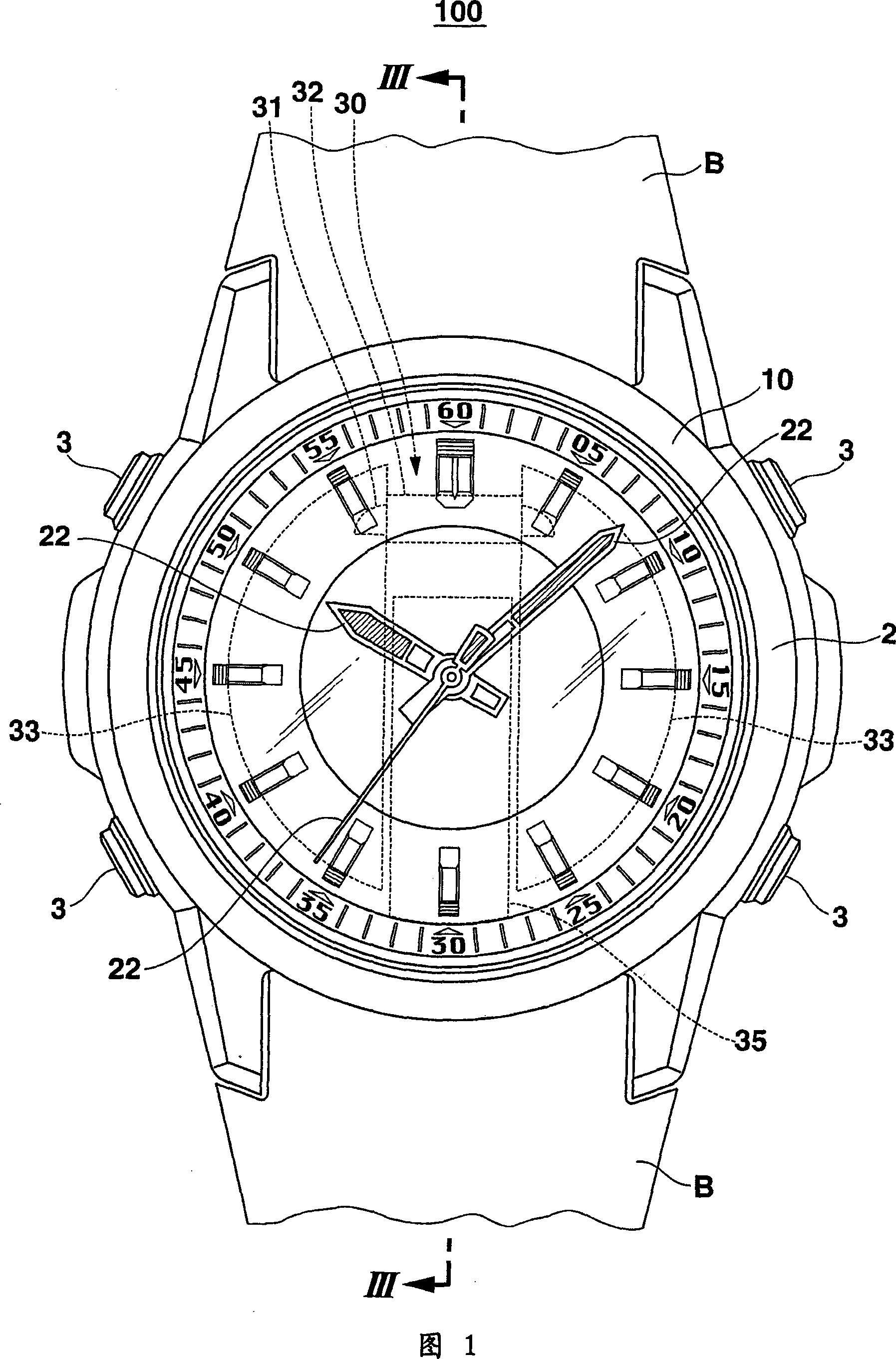
[0029] As shown in FIGS. 1 and 3 , the wristwatch 100 has a device body 2 , and a strap B is attached to the upper and lower ends of the device body 2 , that is, at the 12 o'clock side end and the 6 o'clock side end.

[0030] In addition, a switch 3 for instructing execution of various functions of the wristwatch 100 is provided on the outer peripheral portion of the instrument body 2 .

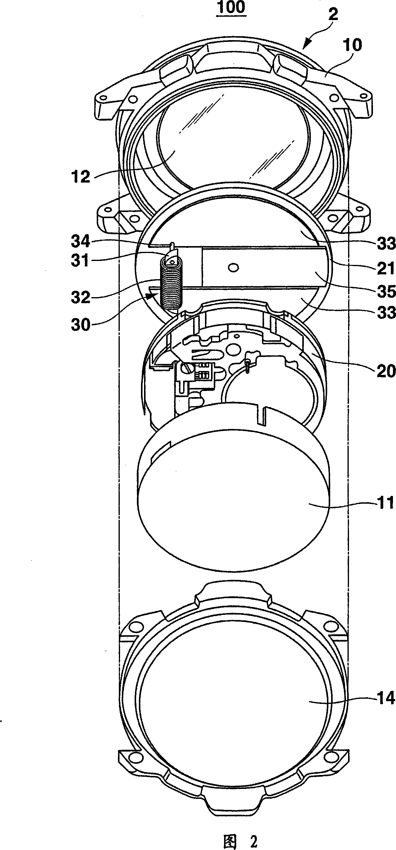
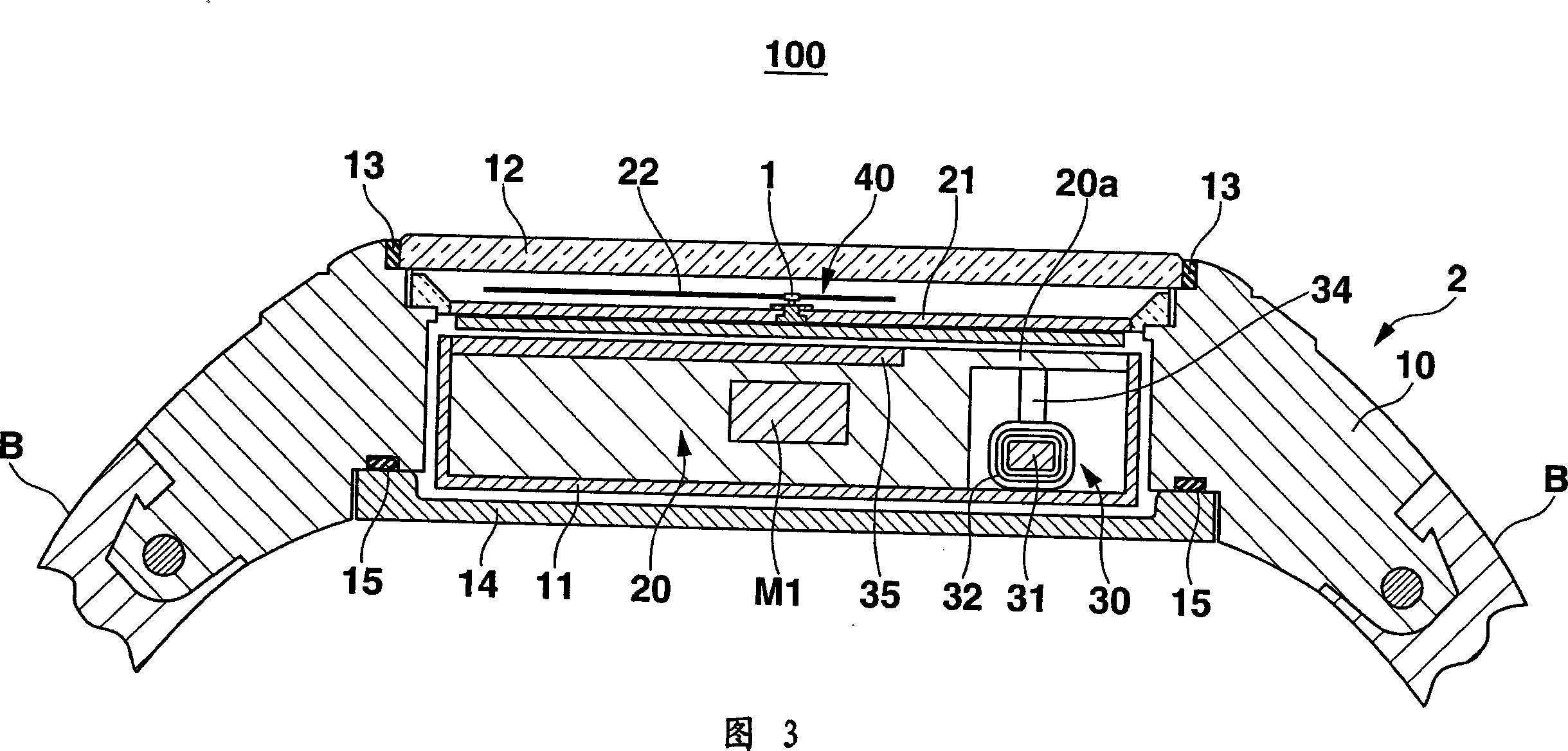
[0031] As shown in FIGS. 1 to 3 , the instrument body 2 has a watch case 10 made of a metal cylindrical frame such as titanium or stainless steel as an upper seal that closes the upper opening of the watch case 10 with a seal 13 . The watch glass 12 of the component, the dial 21 arranged under the watch glass 12, is made of the same material as the watch case 10 and uses the O-ring 15 as the bottom cover of the lower closing member that closes the lower opening of the watch case 10 14.

[0032] The inside of the watch case 10 accommodates the antenna device 30 for receiving standard radio wa...

Embodiment approach 2

[0061] Next, regarding Embodiment 2 of the present invention, the differences from Embodiment 1 will be mainly described.

[0062] As shown in FIGS. 10 and 11 , the wristwatch 200 has a watch body 2 , and a band B is attached to upper and lower ends of the watch body 2 .

[0063] As shown in FIG. 11, the watch main body 2 has a watch case 10 in a cylindrical frame as a watch case for closing the watch case.

[0064] The watch glass 12 of the upper closing member of the upper opening of 10, the text set under the watch glass 12

[0065] The dial 21 is the bottom cover 14 serving as a lower closing member for closing the lower opening of the watch case 10 .

[0066] The inside of the watch case 10 accommodates an antenna device 70 for receiving standard radio waves, an analog pointer mechanism 40, a motor M for driving the analog pointer mechanism 40, and a reception control device connected to these and controlling the antenna device 70 and the analog pointer mechanism 40 The...

Deformed example 2-1

[0073] Next, with regard to Modification 2-1 of Embodiment 2 in FIG. 12 of the present invention, only the parts different from Embodiment 2 will be mainly described.

[0074] As shown in FIG. 13 , motors M1 to M3 are arranged below the first outer magnetic body 73 in the frame 20 . In addition, a motor M4 is disposed below the second outer magnetic body 74 .

[0075] In this way, the first external magnetic body 73 and the second external magnetic body 74 of the antenna device 70 shield the magnetic force from the outside by sharing, and the external magnetic force is difficult to reach the plurality of motors M1-M4, so the impact of the external magnetic force on each motor M1-M4 can be reduced. influence, can improve the accuracy of the table.


PUM


Abstract

In an antenna device of a wristwatch, a pair of external magnetic members each attached to a respective one of both ends of a magnetic core effectively collects the magnetic flux of a standard time and frequency signal. The collected magnetic flux passes through the core around which a coil is wound, thereby inducing an electromotive force and hence improving the reception accuracy of the signal. The pair of external magnetic members screens out undesirable external magnetism which would otherwise influence motors that drive a hand shaft and hands, thereby achieving accurate hand driving and improving the high watch accuracy.

Description

technical field [0001] The present invention relates to an electronic instrument with radio wave receiving function and an electronic clock which corrects time according to standard radio wave. Background technique [0002] As one type of electronic equipment, there is known an electronic timepiece that receives standard radio waves including time information and automatically corrects the current time. In such electronic timepieces, an antenna device in which a coil is wound around an iron core made of amorphous metal, ferrite, etc. as a magnetic material is widely used as an antenna device for receiving standard radio waves. [0003] On the other hand, in the case of a timepiece whose hands are driven by an electric motor, the accuracy of the timepiece is often reduced due to the influence of external magnetic force unnecessary for the control of the timepiece on the driving of the hands. Therefore, maintaining the accuracy of the timepiece is sought by providing a magnet...

Claims


Application Information

Patent Timeline
Patent Type & Authority Applications(China)
IPC IPC(8): H01Q7/08G04C3/00G04C3/14G04G21/04G04R60/10H01Q1/22
Inventor 阿部和明染谷薰木村壮
Owner CASIO COMPUTER CO LTD
Why Eureka
Try Eureka