Hydrostatic drive and method for braking a hydrostatic drive

A hydrostatic, drive technology used in transmission control, elements with teeth, belts/chains/gears, etc.

Active Publication Date: 2008-04-02
BOSCH REXROTH AG
View PDF0 Cites 18 Cited by
  • Summary
  • Abstract
  • Description
  • Claims
  • Application Information

AI Technical Summary

Problems solved by technology

[0004] A disadvantage of the described drive system is that, in addition to the hydraulic pump and the hydraulic mo

Method used


Image

  • Hydrostatic drive and method for braking a hydrostatic drive
  • Hydrostatic drive and method for braking a hydrostatic drive
  • Hydrostatic drive and method for braking a hydrostatic drive

Examples


Embodiment Construction

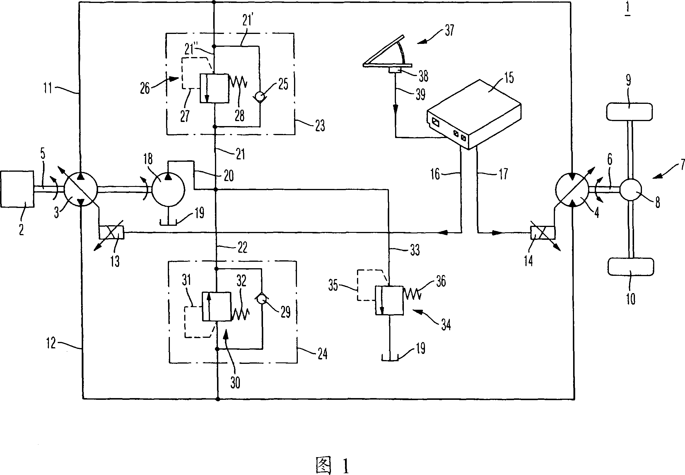
[0018] A hydrostatic drive according to the invention is shown in FIG. 1 . A drive motor 2 is used as the main drive source, usually in the form of an internal combustion engine, preferably a diesel internal combustion engine. The hydrostatic drive 1 according to the invention may for example be a hydrostatic transmission for a hydrostatically driven vehicle such as a forklift or a construction machine, but the invention is not limited to such drives.

[0019] The drive motor 2 drives the variable displacement hydraulic pump 3 . The variable displacement hydraulic pump 3 is designed for transmission in both directions and is preferably an axial piston machine of inclined shaft or swash plate design. The hydraulic motor 4 is connected to the hydraulic pump 3 in a closed circuit. The hydraulic motor 4 is likewise designed to work in both flow directions. The absorption capacity of the hydraulic motor 4 is also adjustable.

[0020] In order to drive the hydraulic pump 3 , the...


PUM


Abstract

The invention relates to a hydrostatic drive (1) and a method for braking a hydrostatic drive (1). In the hydrostatic drive (1), a hydraulic pump (3) is connected to a hydraulic motor (4) by means of a first and a second working line (11, 12). The hydrostatic drive (1) comprises a brake actuating device (37) on at least one pressure relief valve (26, 30) which is connected to the working line arranged downstream of the hydraulic motor (4). The brake pump volume of the hydraulic pump (3) can be regulated upon detection of an actuation of the brake actuation device (37). The hydraulic motor (4) is regulated according to the actuation intensity of the brake actuation device (37) in order to achieve larger absorption volumes, when the actuation intensity of the brake actuation device (37) increases.

Description

technical field [0001] The invention relates to a braking method for a hydrostatic drive and to such a hydrostatic drive. Background technique [0002] Hydrostatic drives are often used to drive hydraulic systems for tool operation or vehicle drive systems in construction site vehicles. In this case, a main drive source such as an internal combustion engine is connected to at least one hydraulic pump. To drive the vehicle, a hydraulic motor is mostly connected in a closed circuit to such a hydraulic pump. Due to the mass inertia of the vehicle, during braking of the vehicle, the hydraulic motor driven through the vehicle wheels thereafter acts as a pump and transmits pressure medium in a closed hydraulic circuit without reversing the direction of flow. Accordingly, a hydraulic pump carrying pressure medium on its intake side acts accordingly as a hydraulic motor and generates an output torque counteracting the action of the internal combustion engine. [0003] In vehicles...

Claims


Application Information

Patent Timeline
IPC IPC(8): F16H61/42F16H59/54B60W10/18B60W30/18B60W10/10F16H61/423
Inventor 马丁·贝姆
Owner BOSCH REXROTH AG
Why Eureka
Try Eureka