A display method of B/M mode ultrason image

An ultrasound image and display method technology, applied in image enhancement, image data processing, instruments, etc., can solve the problems of complex hardware circuit, complicated PCB board wiring, complicated image post-processing calculation, etc., to save hardware cost and facilitate post-processing. , the effect of reducing the size

Inactive Publication Date: 2008-04-09
SHENZHEN LANDWIND IND
View PDF0 Cites 6 Cited by
  • Summary
  • Abstract
  • Description
  • Claims
  • Application Information

AI Technical Summary

Problems solved by technology

[0006] The technical problem to be solved by the present invention is to provide a B/M mode ultrasonic image display method, which overcomes the fact that B mode and M mode ultrasonic image display in the prior art...

Method used


Image

  • A display method of B/M mode ultrason image
  • A display method of B/M mode ultrason image
  • A display method of B/M mode ultrason image

Examples


Embodiment Construction

[0042] Below according to accompanying drawing and embodiment the present invention will be described in further detail:

[0043] 1. Pretreatment of B-ultrasound and M-ultrasound

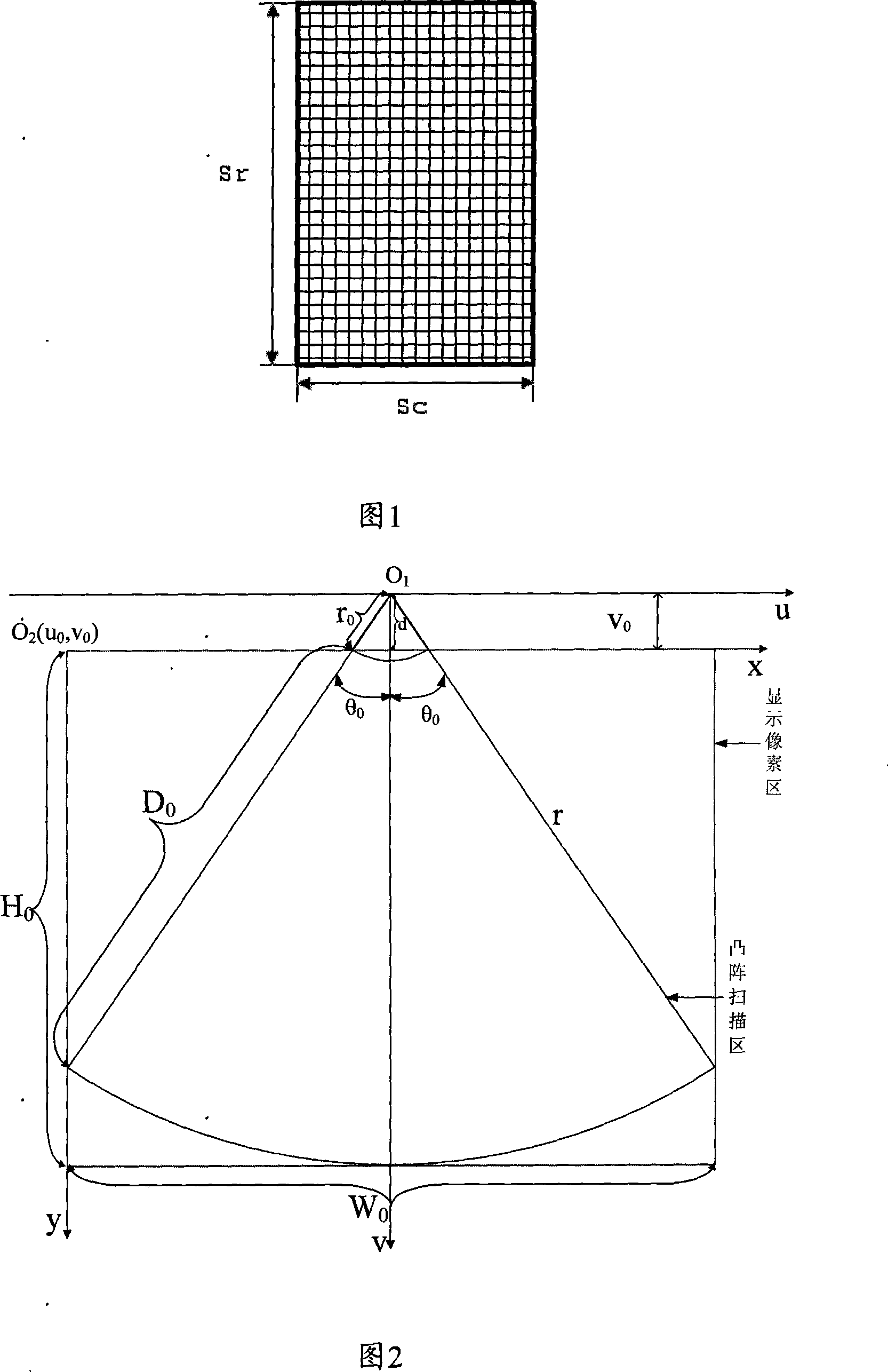
[0044] The format and size of the sampling data are stored as shown in Figure 1. There are a total of Sr rows and Sc columns, and the size is Sr×Sc Byte. The sampling data on each row corresponds to the same scanning depth. From the first row to the Srth row, the corresponding scanning depth increases from zero to the set maximum scanning depth of the probe in equal intervals. The sampling data on each column corresponds to the same scanning angle, from the first column to the Sc column, as shown in Figure 2 and Figure 4, the corresponding scanning angles are sequentially and equally spaced from -θ 0 increase to θ 0 . Table 1 lists the parameters that need to be acquired, set and pre-calculated.

[0045] Table 1

[0046] parameter name

Definition of parameters

symbol

...


PUM


Abstract

The invention relates to a B/M mode ultrasonic image display method which comprises the following procedure: A1,the arrangement directions and the display scales of a B model ultrasonic image and an M model ultrasonic image on a screen are determined; A2, a software module is utilized to display the B model ultrasonic image on the screen; A3, an M sampling line is selected on the B model ultrasonic image; A4, the software module is utilized to display the B model ultrasonic image corresponding to the M sampling line on the screen. The invention uses software to perform the DSC treatment and to perform the display of the B/M model ultrasonic image, a hardware processing module of DSC is omitted, the hardware cost is saved, the hardware volume is reduced, and the great convenience is provided for the post-treatment of the image.

Description

technical field [0001] The invention relates to the technical field of ultrasonic diagnostic equipment, in particular to a B / M mode ultrasonic image display method. Background technique [0002] The current B-ultrasound DSC is usually implemented by hardware, so for image display, the specific M-mode display is also implemented in hardware. To implement scan conversion by hardware, two frame memories need to store the image data in the sound beam scanning format. The two frame memories adopt the "ping-pong" working mode. When one frame memory writes the current echo data according to the sound beam scanning timing, The other frame memory reads data at the display clock rate, and the read data is subjected to two-dimensional linear interpolation to obtain the value of the display pixel. Whenever the sound beam scanning completes a cycle, the "ping-pong" switching of the two frame memories is performed. According to the frequency of the display clock, a display pixel is outp...

Claims


Application Information

Patent Timeline
IPC IPC(8): A61B8/14G06T5/00
Inventor 程延俊陈闽峰
Owner SHENZHEN LANDWIND IND
Why Eureka
Try Eureka