Main blowing system for weft insertion

A technology of weft insertion and main nozzle, used in textile, textile and papermaking, looms, etc., can solve the problems of accelerating weft yarn, lowering, high jetting speed, etc., to achieve high airflow jetting speed, improved ability, and increased pressure.

Inactive Publication Date: 2008-04-09
JIANGSU WANGONG TECH GRP CO LTD
View PDF0 Cites 5 Cited by
  • Summary
  • Abstract
  • Description
  • Claims
  • Application Information

AI Technical Summary

Problems solved by technology

The current main jet system for weft insertion generally consists of an air storage tank, a main nozzle, and a solenoid valve that controls the on-off of the air flow. It can only control the on-off of the air flow, but cannot boost the air flow. When the gas passes through the pipeline and the solenoid valve and reaches the main nozzle, the air pressure has been reduced, so a higher jet speed cannot be obtained, which affects the ability to accelerate the weft yarn

Method used


Image

  • Main blowing system for weft insertion

Examples


Embodiment Construction

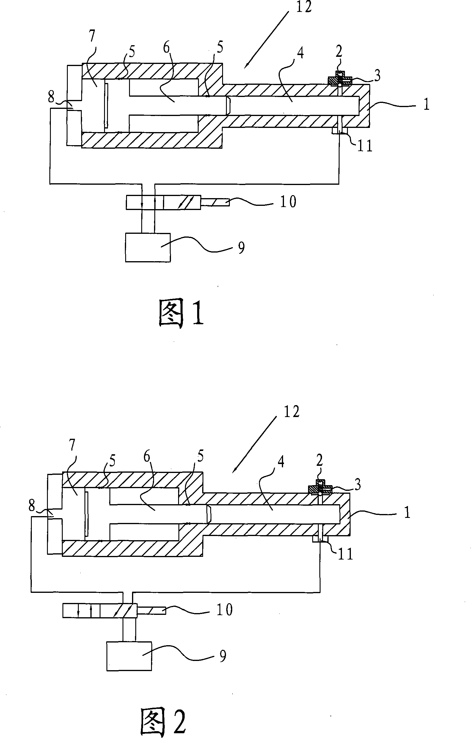
[0012] A main air injection system for weft insertion, including an air storage tank 9 for containing high-pressure gas, a main nozzle 3 for injecting high-speed air flow, and a solenoid valve connecting the air storage tank 9 and the main nozzle 3 and used to control the on-off of the air flow 10. In order to increase the air supply pressure of the main nozzle 3, a supercharger 12 is arranged between the solenoid valve 10 and the main nozzle 3 in the present invention. The piston 6 inside the device body 1 and can slide along the inner cavity of the supercharger body 1, the inner cavity of the supercharger body 1 is divided into the first air chamber 4 and the second air chamber 7 by the piston 6, in order to increase the piston 6 and the booster The tightness of the pressurizer body 1, in this embodiment, an O-ring 5 is used to seal between the piston 6 and the inner cavity of the booster body 1 . The cross-sectional area of ​​the first air chamber 4 is smaller than the cros...


PUM


Abstract

The invention relates to a main air-jet system used for weft insertion. The invention comprises a gas-holder used for holding high pressure gas, a chief nozzle used for spraying high speed air flow, and a solenoid valve which is connected with the gas-holder and the chief nozzle and used for controlling on-off of air flow. A pressure intensifier is arranged between the solenoid valve and the chief nozzle, and the pressure intensifier comprises a hollow pressure intensifier body and a piston which is arranged in the pressure intensifier body and slides along an inner cavity of the pressure intensifier body. The inner cavity of the pressure intensifier body is separated into a first air chamber and a second air chamber by the piston. The cross-sectional area of the first air chamber is smaller than the cross-sectional area of the second air chamber. A one-way valve arranged on the first air chamber conducts to the chief nozzle by a single way. At least two communicating states exist among the first air chamber, the second sir chamber, the gas- holder and atmosphere: under the first communicating state, the gas-holder conducts to the first air chamber and the second air chamber respectively; under the second communicating sate, the second air chamber conducts to atmosphere. The main air-jet system used for weft insertion can not only regulate the on-off of the air flow, but also increase the air flow pressure of the chief nozzle to obtain a larger jet velocity of the air flow and to improve the performance of accelerating weft.

Description

technical field [0001] The invention relates to a main air injection system for weft insertion on an air jet loom. Background technique [0002] High-speed airflow is commonly used for weft insertion in air-jet looms, and the main function of the main jet airflow is to accelerate the weft yarn. Using the high speed and stability of the main jet airflow, the weft yarn will be accelerated to the required flight speed, so the speed of the airflow has a great influence on the weft yarn. Flight speed has an important effect. The current main jet system for weft insertion generally consists of an air storage tank, a main nozzle, and a solenoid valve that controls the on-off of the air flow. It can only control the on-off of the air flow, but cannot boost the air flow. When the gas passes through the pipeline and the solenoid valve and reaches the main nozzle, the air pressure has been reduced, so a higher jet speed cannot be obtained, which affects the ability to accelerate the w...

Claims


Application Information

Patent Timeline
Patent Type & Authority Applications(China)
IPC IPC(8): D03D47/30D03J1/04
Inventor 周平祝章琛
Owner JIANGSU WANGONG TECH GRP CO LTD
Why Eureka
Try Eureka