Ventilation window locking device

A locking device, ventilation window technology, applied in ventilation layout, roof, building fastening devices, etc., can solve the problems of inconvenient production and assembly, high production cost, complex structure, etc., to expand the technical scope, convenient production and assembly, structural simple effect

Inactive Publication Date: 2008-04-09
董志君
View PDF7 Cites 21 Cited by
  • Summary
  • Abstract
  • Description
  • Claims
  • Application Information

AI Technical Summary

Problems solved by technology

However, this structure has several obvious disadvantages: first, its internal structure uses a series of spring combinations, and there is obvious noise during the switching process; The function of freely adjusting the size of the vent with multiple gears is more inconvenient to use, especially when the outdoor weather is relatively bad; finally, the ventilation plate is not only connected with the ratchet device, but also connected with the outer frame, so the structure is more complicated and the production Assembly is extremely inconvenient and production cost is high

Method used


Image

  • Ventilation window locking device
  • Ventilation window locking device
  • Ventilation window locking device

Examples


Embodiment 1

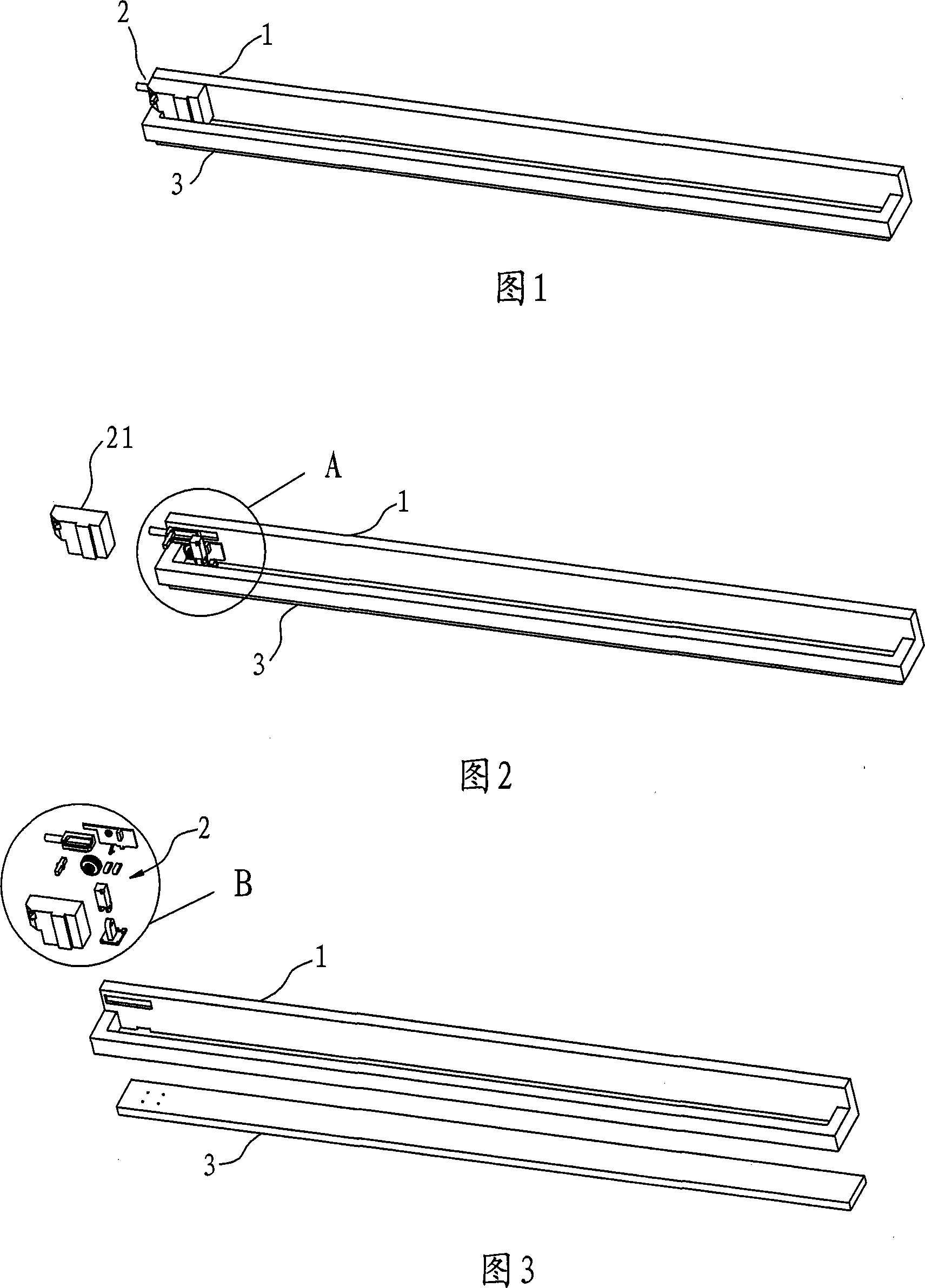
[0051] Embodiment 1: With reference to Figure 1, Figure 2 and Figure 3, the ventilation window locking device 2 in this embodiment is installed on the left side of the top end of the inner frame 1, or can be installed on the right side of the top end of the inner frame 1, or Install together.

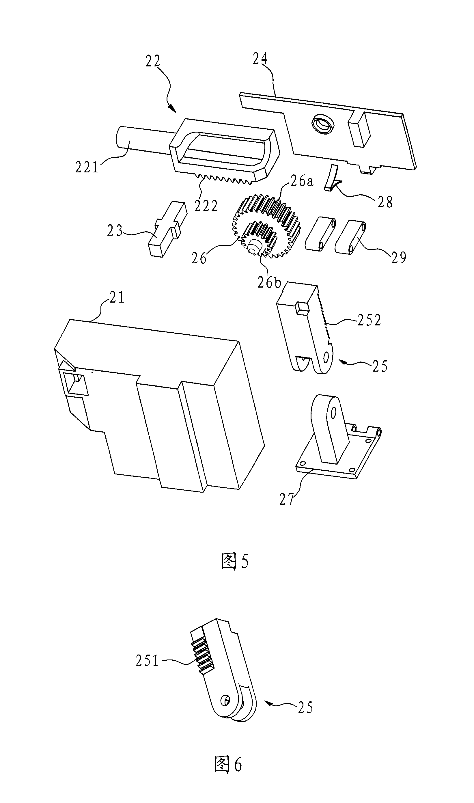
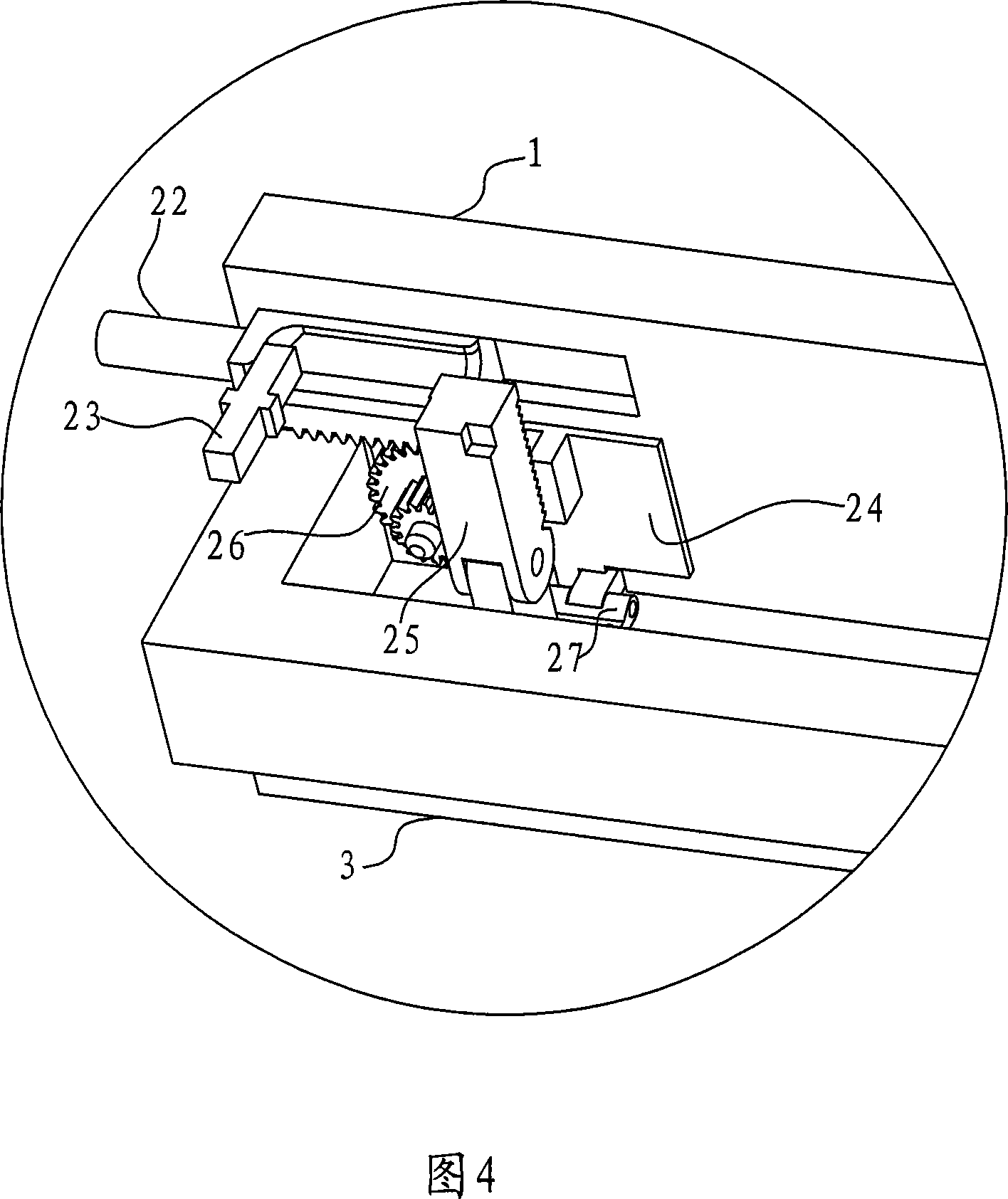
[0052] 4 and 5, the ventilation window locking device in this embodiment is composed of a housing 21, a pull rod rack 25, a pin 22, a positioning pin 23, a base 24, a valve plate 28, and a transmission gear mechanism 26.

[0053] The housing 21 has an accommodating space, the transmission gear mechanism 26 and the valve disc 28 are encapsulated on an outer frame 99 fixed, and the pull rod rack 25 and the plug 22 extend out of the housing 21 and can move back and forth.

[0054]The tie rod rack 25 is connected to the ventilation plate 3 through a connecting piece 27, the tie rod rack 25 is hinged with the connecting piece 27, and the connecting piece 27 is fixed on the ventilation plate 3 by...

Embodiment 2

[0061] Embodiment 2: As shown in FIG. 8, the base 24 in this embodiment is provided with a sliding rail 241 for the pin 22 to move back and forth, and the rest is the same as the embodiment 1.

Embodiment 3

[0062] Embodiment 3: As shown in FIG. 9, FIG. 10 and FIG. 11, the transmission gear mechanism 26 in this embodiment includes a first gear 261 and a second gear 262 meshing with the first gear 261. The first gear 261 is The gear input end that meshes with the longitudinal rod gear teeth 252, and the second gear 262 is the gear output end that meshes with the latch gear teeth 222. In addition, the movement direction of the plug 22 is perpendicular to the longitudinal direction of the ventilation plate 3, which is suitable for the structure where the plug hole 98 is opened on the outer frame 99 along the top to facilitate the back and forth movement of the plug 22 through two guide posts 22a vertically arranged on the base 24. Others are the same as in Example 1.


PUM


Abstract

The invention relates to a locking device used for a ventilation window. The invention is characterized in that the device comprises a pull rod rack (25) connected with a ventilation board (3), and a vertical pull rod wheel-tooth (251) is arranged on one lateral side of the pull rod rack; the device also comprises a pin (22) which is provided with an inserting end (221) and can be inserted into an outer frame pin hole (98), and a pin wheel-tooth (222) is arranged on one lateral side of the pin, and the arranging direction of the pin wheel-tooth (222) is vertical to a length direction of the pin (22); the device also comprises a transmission gear device (26) which comprises a gear input end meshed with the vertical pull rod wheel-tooth (251) of the pull rod rack and a gear output end meshed with the pin wheel-tooth (222). Compared with the prior art, the invention has the advantages that the adoption of the transmission gear device simplifies the structure of the ventilation window locking device, and results in a more prompt manufacturing and assembling process and largely reduces the manufacturing cost; the abandonment of a traditional spring control mode can eliminate the noise caused by springs.

Description

Technical field [0001] The utility model relates to a locking device between an inner window frame and an outer window frame of a ventilating window, in particular to a ventilating window locking device capable of realizing multi-section ventilation control. Background technique [0002] Among the various known roof window designs, the roof window with locking device achieves indoor and outdoor ventilation and opening and closing functions by opening or closing the ventilation panel. The principle is that the upper part of the outer frame is equipped with and The pawl device connected to the ventilating plate, the pawl device is a series of combinations of internal springs to make the ventilating plate connected to the brake slide to reach two strokes. This technology has been published. For details, please refer to the Chinese invention patent: ZL02808065. 3. A "Locking Device for Ventilation Window" (Authorized Announcement Number: CN1217075C) is published. This patent has the ...

Claims


Application Information

Patent Timeline
Patent Type & Authority Applications(China)
IPC IPC(8): E05C1/02E05C19/02E06B7/02
CPCE04D13/0325
Inventor 董志君
Owner 董志君
Why Eureka
Try Eureka