Optical fibre connector

An optical fiber connector and optical fiber technology, which is applied to the coupling of optical waveguides, etc., can solve the problems of easy breakage of quartz glass optical fibers, delay in construction period, affecting connection testing, etc., to achieve easy maintenance and replacement, speed up docking, and improve docking efficiency Effect

Active Publication Date: 2008-04-09
杭州万隆光电设备股份有限公司
View PDF0 Cites 15 Cited by
  • Summary
  • Abstract
  • Description
  • Claims
  • Application Information

AI Technical Summary

Problems solved by technology

This type of optical fiber connector requires precise processing for the connecting tube; the optical fiber is generally very brittle, and the quartz glass optical fiber is easily broken. Once the optical fiber is broken in the tube, it is extremely difficult to take out the broken optical fiber, which

Method used


Image

  • Optical fibre connector
  • Optical fibre connector
  • Optical fibre connector

Examples


Embodiment Construction

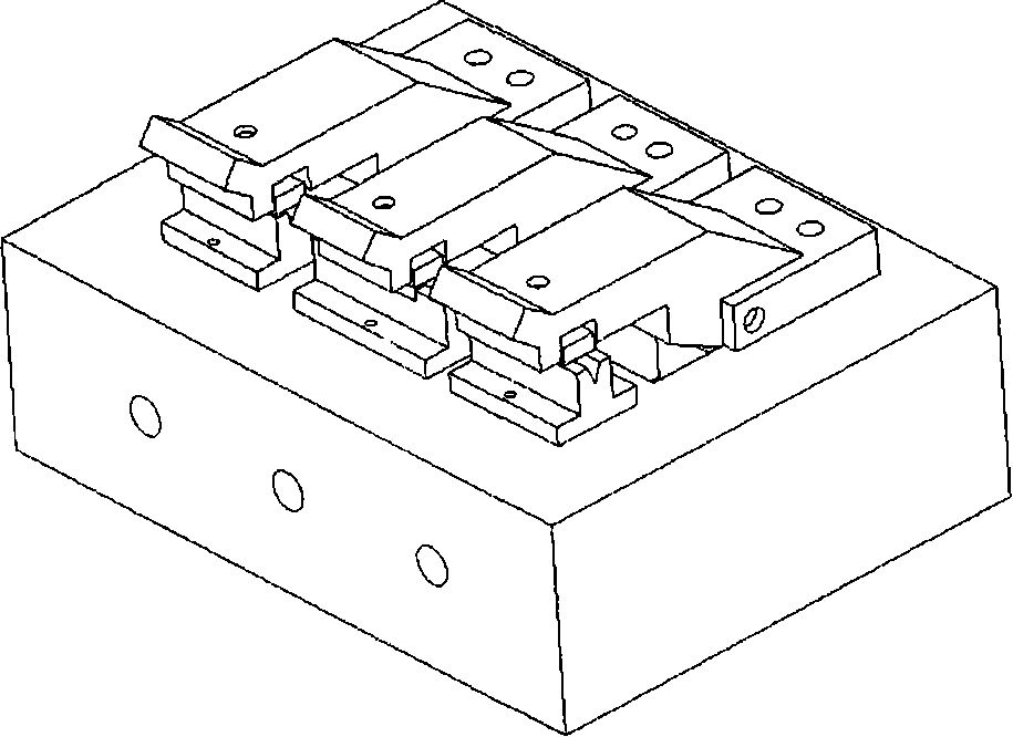
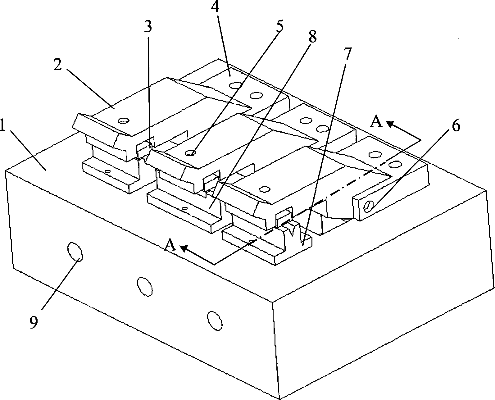
[0017] Such as image 3 and Figure 4 As shown, a fiber optic connector disclosed by the present invention includes: a base 1, the upper bottom surface of the base 1 near the front end is fixed with a V-shaped groove 7 on the left and a right and a V-shaped groove 8 in the middle. The V-shaped groove is used to accommodate the reference optical fiber and the optical fiber to be tested; three concave plates 4 are fixed on the bottom surface of the base 1 near the rear end surface, the concave surface of the concave plate 4 faces the front end of the base 1, and the rear end of the pressure plate 2 is placed into the In the recess of the concave plate 4, three shafts 6 on the right side of the concave plate 4 connect the three concave plates 4 with the three pressure plates 2 respectively, and the upper bottom surface of the pressure plate 2 is provided with a threaded hole near the front end. The pressing plate 2, the optical fiber compaction adjustment spring 5 located in the...


PUM


Abstract

An optical fiber connector consists of a base and three V-shape slots fixed on the base, which is used for containing reference optical fiber and tested optical fiber. Three concave plates with a concave surface oriented to the front head face of the base are fixed on the base, the rear part of a pressure pad is inserted into the concave positions of the concave plates, and the concave plates and the pressure pad are connected by three axes running through the right side of the concave plates. The pressure pad is provided with screwed holes, and the pressure pad, a spring, and a pressure block are connected together by bolts, the optical fiber is tightly pressed at the lower end surface of the pressure pad. A front nest pin and a back nest pin respectively screwed in the screwed holes in the front and back head faces of the base are used for adjusting the travel route of the pressure pad. The optical fiber connector is characterized by rapid connection, long service life, easy maintenance, and reliably fixing the tested optical fiber.

Description

technical field [0001] The invention relates to an optical fiber connector, in particular to an active optical fiber connector with three V-groove structures. Background technique [0002] With the increasing development of optical fiber transmission applications, for those who install, maintain, and test optical waveguide lines and inspectors of optical fiber and cable manufacturers, it is necessary to frequently connect optical fibers. Fiber optic connectors typically use metal, ceramic, rubber, or glass tubes with fine inner diameters to accommodate reference and test fibers. figure 1 It is a schematic diagram of the main part of the active optical fiber connector widely used at present to connect the optical fiber. In the figure, 2 is the above-mentioned glass tube. Let the bare optical fiber 12 extend into a certain place A in the glass tube, then the right optical fiber 3 is removed from the coating 31 in the same way, and the bare optical fiber 32 is inserted into th...

Claims


Application Information

Patent Timeline
IPC IPC(8): G02B6/38
Inventor 龚永祥
Owner 杭州万隆光电设备股份有限公司
Why Eureka
Try Eureka