Chuck used for optical fiber joints

An optical fiber splicer and collet technology, which is applied to the coupling of optical waveguides and other directions, can solve the problems of non-stop function, difficult miniaturization, large overall structure and other problems, and achieves easy insertion, good clamping and fixing, and good guidance. effect of action

Active Publication Date: 2008-04-09
JIANGSU UNIKIT OPTICAL TECH
View PDF0 Cites 2 Cited by
  • Summary
  • Abstract
  • Description
  • Claims
  • Application Information

AI Technical Summary

Problems solved by technology

[0002] At present, the installation of optical fiber cables for optical fiber connection sub-products mainly uses special tools to push the bare fiber by pressing the bent optical fiber sheath, so as to ensure the bonding of the optical fiber surface, and then rely on the single-point clamping device set in the sleeve Tight, the special tool cannot guarantee sufficient bonding force of the optical fiber, especially when the surface of the bare fiber is defective, it is even more difficult to ensure the true bonding of the fiber surface, and it cannot effectively prevent the rotation of the optical fiber cable. When an accidental force is applied during installation or use, it cannot Fully protect bare fiber
There is also a collet used for the connector of the optical fiber ribbon, which is provided with a keyway on the cylinder of the collet. This structure needs to be aligned manually, and the position of the keyway cannot be automatically aligned to realize the anti-rotation function. Ease of miniaturization

Method used


Image

  • Chuck used for optical fiber joints
  • Chuck used for optical fiber joints

Examples


Embodiment Construction

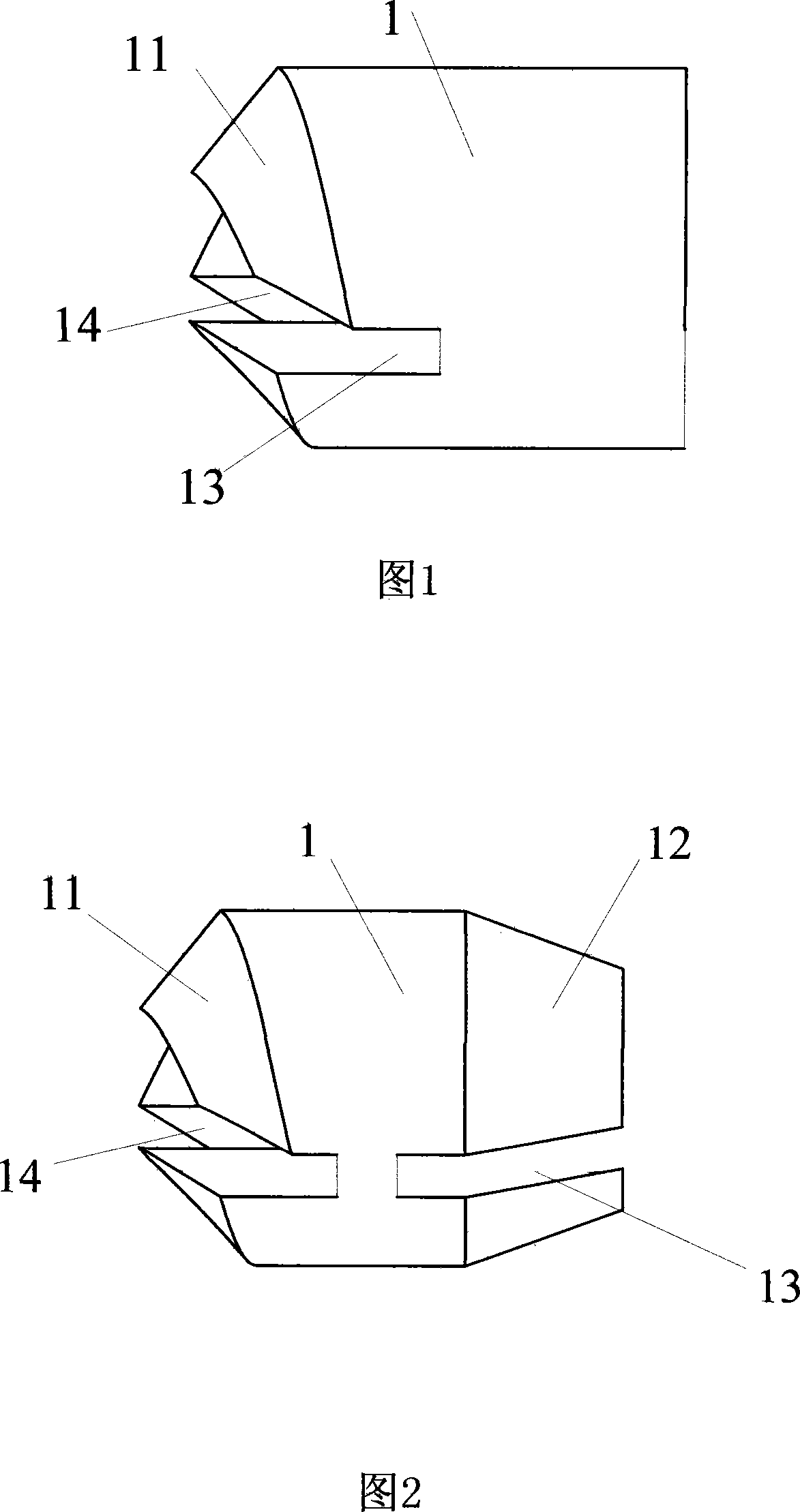
[0022] The present invention will be described in detail below in conjunction with the accompanying drawings.

[0023] As shown in Figure 1, it includes a cylindrical body 1, the body 1 can also be made into a rectangular or other polygonal cylinder, and at the front end of the body 1 are at least two helical surface locking heads 11 formed by dividing the locking groove 13, the The helicoid locking head can also be an equiconic helicoid, that is, a helical surface processed on a conical body, and the taper of multiple locking heads 11 is the same. The number of locking heads can be 2, 3 or 4 according to actual conditions or needs. In the center of the body 1 is an optical fiber hole 14, which is an optical fiber through hole.

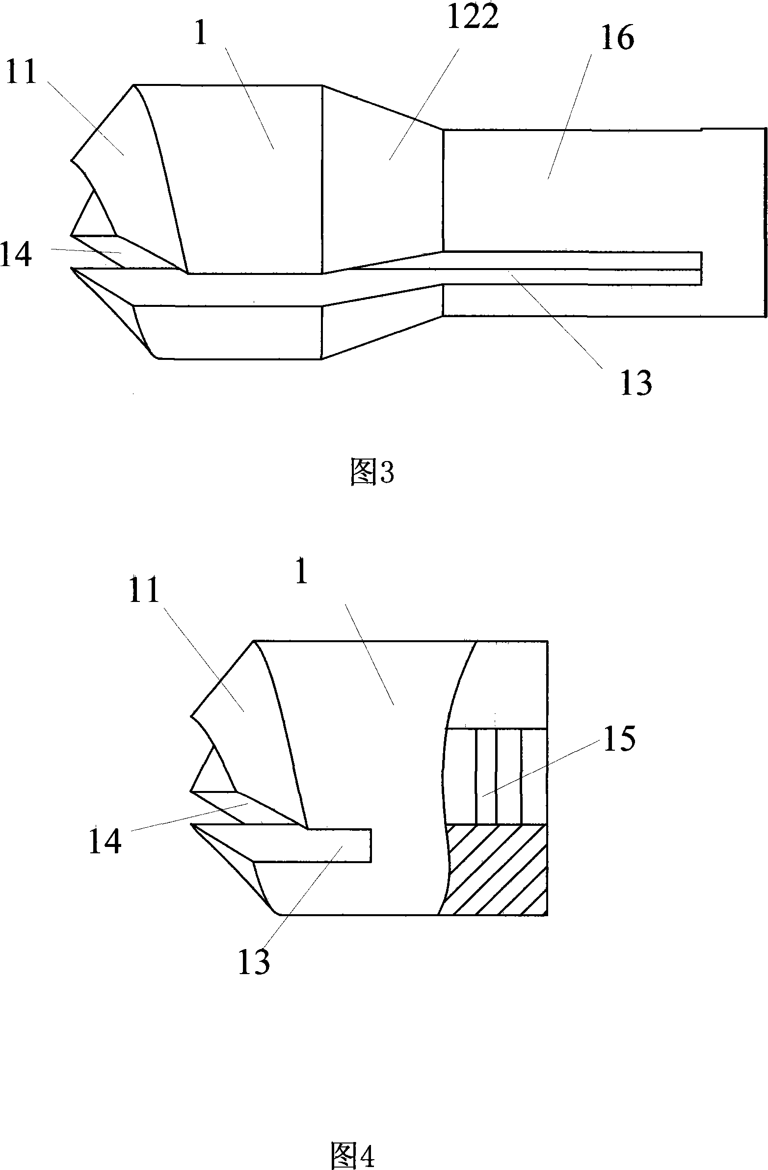
[0024] As an improvement of the present invention, as shown in Figure 2, the rear end of the body 1 is also processed into a cone 12, and a locking groove 13 is also provided on the cone 12, and the conical surface 12 is squeezed during installation. ...


PUM


Abstract

The invention discloses a collet applied for an optical fiber connector. The collet consists of a body with an optical fiber hole, and one end of the body is separated into at least two lock clamps by a lock groove, the surface of the lock clamp is a helicoid which is the helicoid with equal conicity. The other end of the cylinder body is provided with a rear part, and the center of the rear part is also provided with an optical fiber hole. Compared with the prior art, the collet of the invention is provided with at least two lock clamps in the front of the body, the surfaces of the lock clamps are helicoids, and a trap step is formed among the lock clamps. When the collet of the invention is arranged in the optical fiber connector, the helicoid in the front of the collet and a tapering step helicoid in a sleeve of the optical fiber connector rotate, and the two helicoids are engaged with each other automatically, thus effectively preventing the rotation caused during the connection process of the optical fiber; simultaneously, the optical fiber hole in the collet is has the guiding function, thus ensuring the surface of the optical fiber to be undamaged during the connection process. On the other hand, the invention avoids the manual intervention and is favorable for implementing the micromation of the whole structure.

Description

technical field [0001] The invention relates to a component for an optical fiber connector, in particular to a chuck for an optical fiber connector. Background technique [0002] At present, the installation of optical fiber cables for optical fiber connection sub-products mainly uses special tools to push the bare fiber by pressing the bent optical fiber sheath, so as to ensure the bonding of the optical fiber surface, and then rely on the single-point clamping device set in the sleeve Tight, the special tool cannot guarantee sufficient bonding force of the optical fiber, especially when the surface of the bare fiber is defective, it is even more difficult to ensure the true bonding of the fiber surface, and it cannot effectively prevent the rotation of the optical fiber cable. When an accidental force is applied during installation or use, it cannot Fully protect bare fibers. There is also a collet used for the connector of the optical fiber ribbon, which is provided with...

Claims


Application Information

Patent Timeline
Patent Type & Authority Applications(China)
IPC IPC(8): G02B6/38G02B6/36
Inventor 吕根良
Owner JIANGSU UNIKIT OPTICAL TECH
Why Eureka
Try Eureka