

Method for detecting data variation
A data change and data technology, applied in the field of data change detection, can solve problems such as multi-resources, insufficient refresh speed, occupation of computers, etc., achieving the effect of easy implementation, reducing the occupation of precious resources and simple methods
- Summary
- Abstract
- Description
- Claims
- Application Information
AI Technical Summary
Problems solved by technology
Method used
Image

Examples
Embodiment 1
[0027] A method for detecting data changes, comprising the following steps:
[0028] (1) Open up an area as large as the display buffer to be detected as a comparison buffer, then divide the display buffer and comparison buffer into several corresponding buffer blocks, and divide each buffer block All are divided into large network dot diagrams composed of K M×N dot diagrams;
[0029] (2) sub-round scanning shows the network point of buffer block and comparison buffer block then, and every round is divided into K scans, scans the content of display buffer block and comparison buffer block corresponding 1 / K of network point respectively at every turn, Described scanning is to compare one by one whether the content corresponding to each network point on the above two buffer blocks is the same. During each scanning, the content that has been scanned in the current round is no longer repeated scanning, and the K, M and N are all is a positive integer.
[0030] In step (2), if an...
Embodiment 2
[0037] Embodiment 2 Apply the method described in Embodiment 1 to detect the display buffer
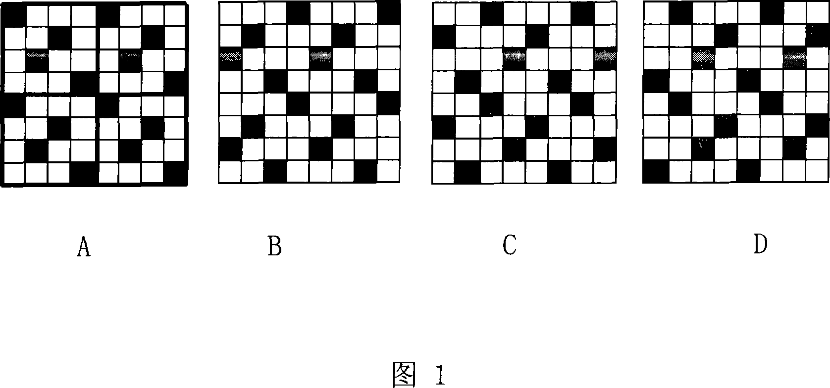
[0038] Each display buffer block and comparison buffer block are divided into a large network dot map composed of 4 4 × 4 network dots, and each scan shows the content of a 1 / 4 network point in the buffer area, and the others are set according to the embodiment. Steps described above. Each scanning site is as shown in Figure 1; Figure 1 is a schematic diagram of the scanning process for each 4 * 4 network point scanning when the method of embodiment 1 is used to detect the display buffer, and each network point schematic diagram has 4 identical 4×4 dot map (where A is the schematic diagram of the first scan, B is the schematic diagram of the second scan, C is the schematic diagram of the third scan, D is the schematic diagram of the fourth scan);
[0039] Black dots will be scanned during this scan, and blank dots will not be scanned. Let's superimpose these 4 scanning dots to see t...
Embodiment 4
[0051] Embodiment 4 Apply the method described in Embodiment 1 to detect the display buffer
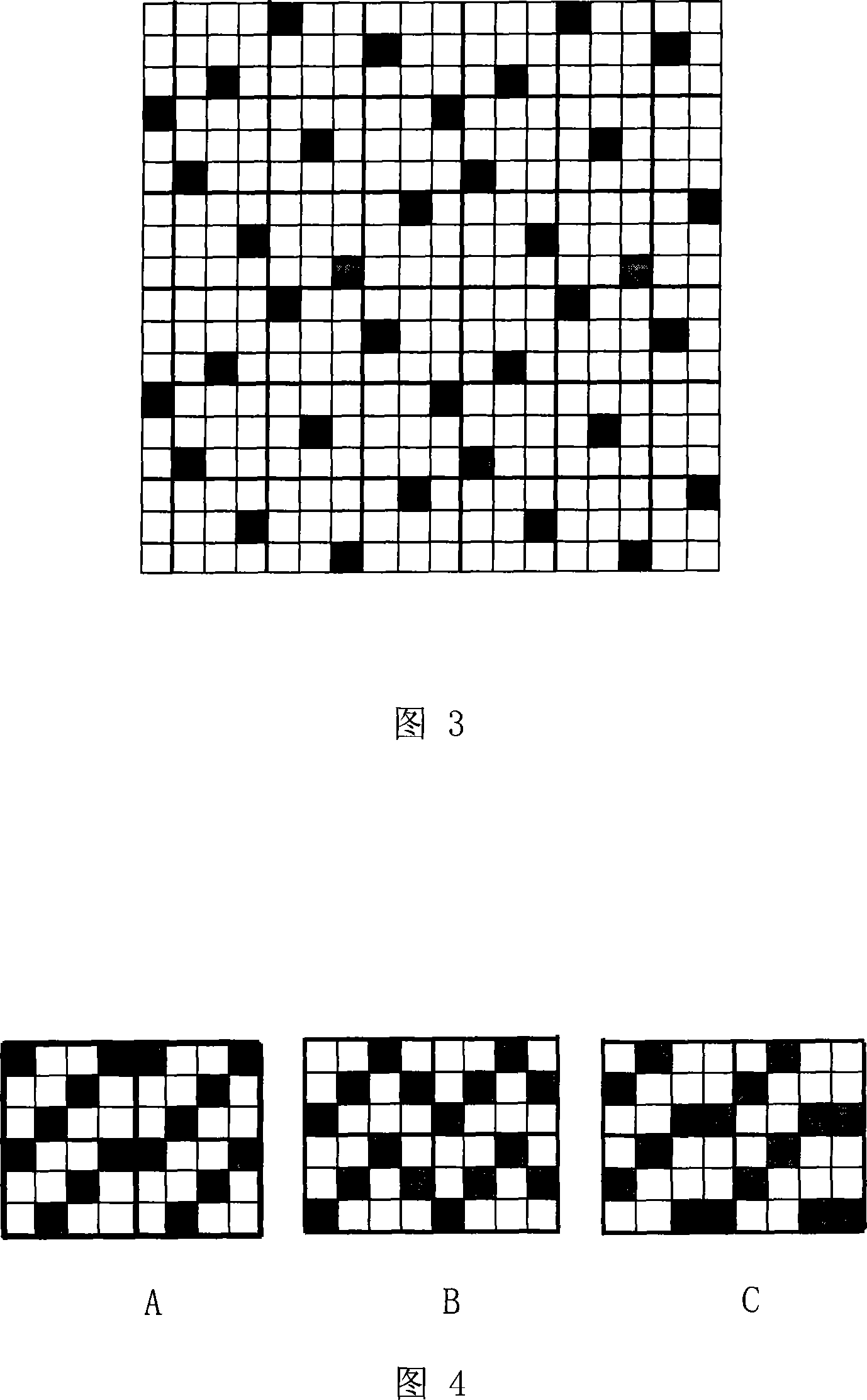
[0052] According to the steps described in Embodiment 1, wherein, the resolution of the display buffer is 25600 × 3072, and the color depth is 16 bits, which is represented by 2 bytes, and is divided into buffer blocks composed of 4 rows and 25 columns. Each buffer The resolution of the blocks is 1024×768. Create an area as large as the display buffer to be detected (25600×3072×2=157286400 bytes) as a comparison buffer (also 157286400 bytes), divide each display buffer block and comparison buffer block It is a large dot diagram composed of three 4×3 dot dot diagrams, each dot represents two pixels in the horizontal direction, and each scan corresponds to the content of one-third of the dots in the display buffer block and the comparison buffer block, Others operate according to the steps described in Example 3. Each scanning site is as shown in Figure 4; Figure 4 is a schematic diag...
PUM
 Abstract
Description
Claims
Application Information