
Simulation checking system and its method for SDH logical design

A technology of simulation verification and logic design, applied in the field of simulation verification, can solve the problems of difficulty in ensuring the accuracy and reliability of analysis results, cumbersome, difficult modular programming, etc., to achieve rigorous and reliable simulation verification results, convenient positioning and debugging, and improve Effects of Simulation Efficiency

Inactive Publication Date: 2008-04-09
UTSTARCOM TELECOM CO LTD
View PDF0 Cites 12 Cited by
  • Summary
  • Abstract
  • Description
  • Claims
  • Application Information

AI Technical Summary

Problems solved by technology

[0004] However, for the first method, it is only suitable for the test situation where the logic design function is relatively simple. Once the function of the logic design is relatively complicated, it is difficult to guarantee the accuracy and reliability of the analysis results by using the waveform observation method, and it is even possible Lead to potential errors in logic design functions; on the other hand, when using programmable logic devices such as FPGAs for logic verification, FPGAs with a huge number of logic gates are required, which are costly and long-term
Moreover, the logic design circuit to be tested must be verified only when the FPGA-based hardware circuit has been debugged; even if the FPGA-based hardware circuit is debugged, once a logic error occurs in the logic design circuit to be tested, the test environment gives There is less help information, and it is very difficult to locate logic errors
For the third method, although rigorous verification results can be obtained, it is quite complicated and cumbersome to use software programming to imitate hardware functions, and because the logic functions implemented by different logic verification projects are different, then for different logic Verification projects need to independently write different behavioral models, which is difficult to achieve modular programming and lacks versatility

Method used


Image

  • Simulation checking system and its method for SDH logical design
  • Simulation checking system and its method for SDH logical design
  • Simulation checking system and its method for SDH logical design

Examples


Embodiment Construction

[0023] Hereinafter, specific embodiments of the present invention will be described in detail with reference to the drawings.

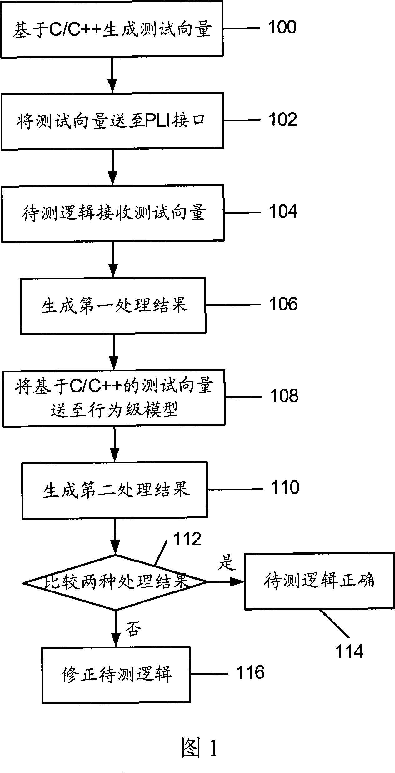
[0024] Fig. 1 shows a schematic structural diagram of a behavior-level model written in C / C++ in the prior art to imitate the logical behavior to be tested. Referring to Figure 1, the implementation principle of the test method is mainly that the test engineer uses the C / C++ high-level programming language to write a behavior-level model to imitate the logic to be tested, and send the same stimulus data used for the test to the logic and behavior to be tested. Level model, compare the results of the two processing. If the processing results are the same, it is determined that the function of the logic behavior to be tested is implemented correctly; if the processing results are inconsistent, the logic to be tested needs to be debugged and corrected. Specifically, it can be explained through the following steps:

[0025] Step 100: Generate a test vector ba...


PUM


Abstract

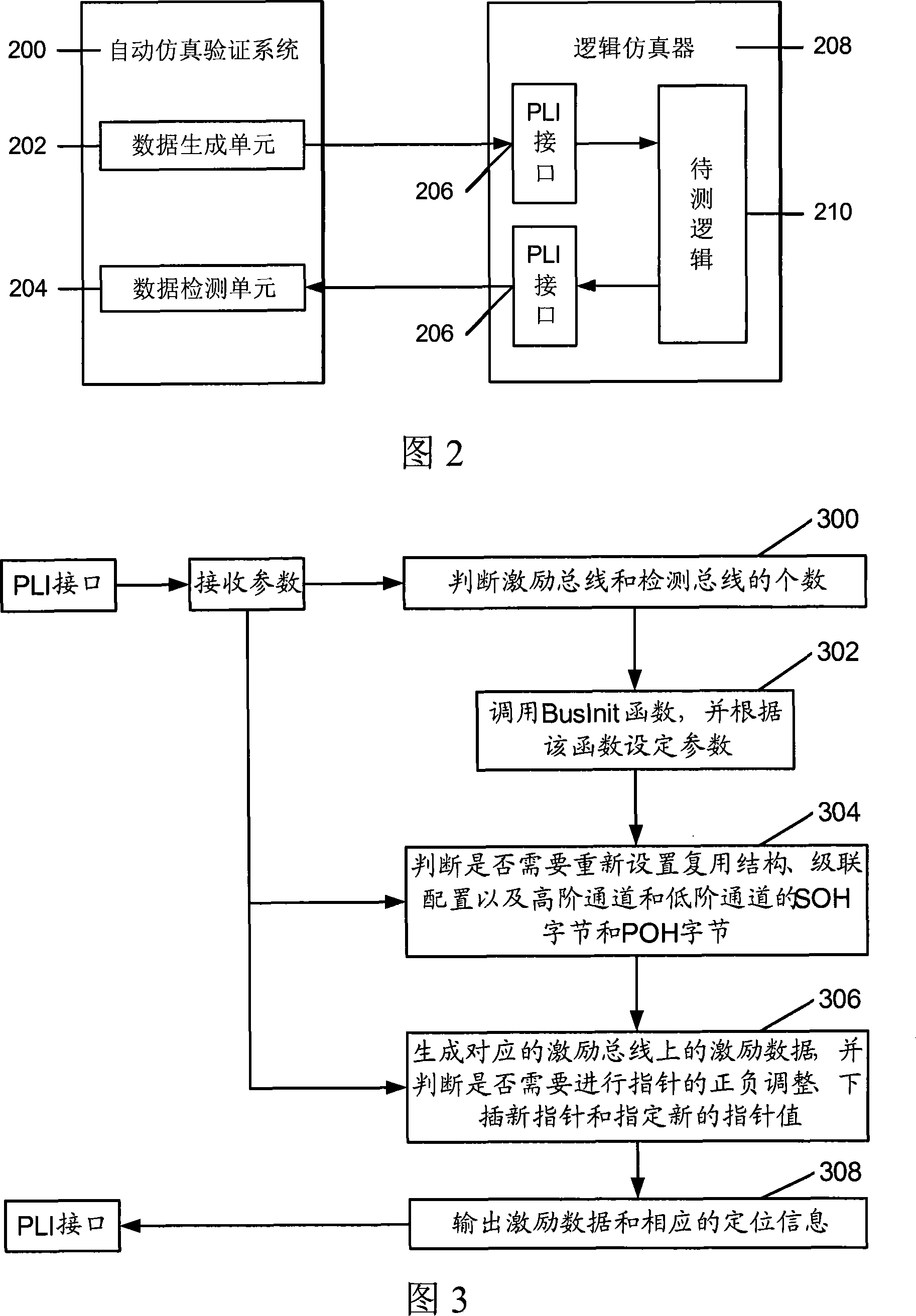
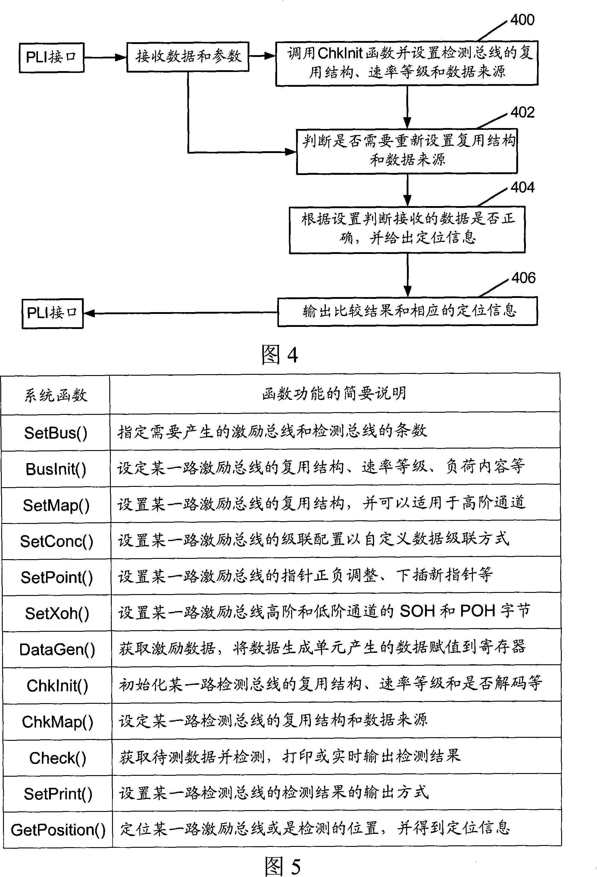
The invention discloses an automatic simulated verification system used for SDH / SONET logical design, which comprises a data generation unit for generating excitation data and positioning information, and a data detection unit for receiving the processed data of the logic to be test. The invention also discloses an automatic simulated verification method. The method comprises: determining the excitation bus and detection bus in the system, setting the corresponding configuration of the excitation bus, generating the excitation data and judging whether to adjust and process the pointer; outputting the excitation data and the corresponding positioning information; setting the corresponding configuration of the detection bus; and judging whether the data received by the detection bus is correct. The inventive system and method can rapidly, simply and efficiently provide a stimulating effect, realize the real-time detection of processed data of the logic to be test, and give an alarm when detecting logic error, thereby facilitating a user to position and modulate the logic error.

Description

Technical field [0001] The present invention relates to logic design technology in the field of optical communications, in particular to a simulation verification technology for logic design circuits in the field of optical communications. Background technique [0002] At present, in the optical synchronous digital transmission system, with the widespread application of large-scale logic circuits and the increasing complexity of logic functions, the test scheme for verifying whether the logic functions are correct has become very complicated and cumbersome. As a result, for logic design verification engineers, the problem of how to simply and efficiently determine whether the logic circuit functions are correct has become more prominent, and it has also become a major difficulty in the current simulation verification technology of logic design circuits. [0003] In the prior art, there are mainly the following test schemes to verify whether the logic design circuit is correct. On...

Claims


Application Information

Patent Timeline
IPC IPC(8): H04B10/08H04J3/16H04J3/06H04B10/07
Inventor 王文华
Owner UTSTARCOM TELECOM CO LTD
Learn More