Magnetically mounted vibration impact transducer

A sensor and magnetic technology, which is applied in the field of equipment fault diagnosis and magnetically installed vibration and shock sensors, can solve problems such as difficult to receive high-frequency vibration and shock, loose connection failure, and tight fit

Active Publication Date: 2008-04-16
北京唐智科技发展有限公司
View PDF0 Cites 26 Cited by
  • Summary
  • Abstract
  • Description
  • Claims
  • Application Information

AI Technical Summary

Problems solved by technology

Its disadvantage is that the scheme of connecting the existing sensor and magnet with a single bolt is prone to loose connection and failure, especially the combined contact surface between the magnet and the sensor is difficult to receive high-frequency vibration and shock due to poor contact and tight fit. It is stipulated by traditional regulations that it can only be used to detect low-frequency vibration with small acceleration; while the glued installation method is formed because it is difficult to squeeze out excess glue by applying pressure for a long time after filling the glue between the sensor and the machine and waiting for it to dry. A very thick or even loose rubber isolation layer affects the transmission of vibration shock and long-term reliability. It is also stipulated by traditional regulations that it can only be used for short-term detection of low-frequency vibration with small acceleration.

Method used


Image

  • Magnetically mounted vibration impact transducer
  • Magnetically mounted vibration impact transducer
  • Magnetically mounted vibration impact transducer

Examples


Embodiment 1

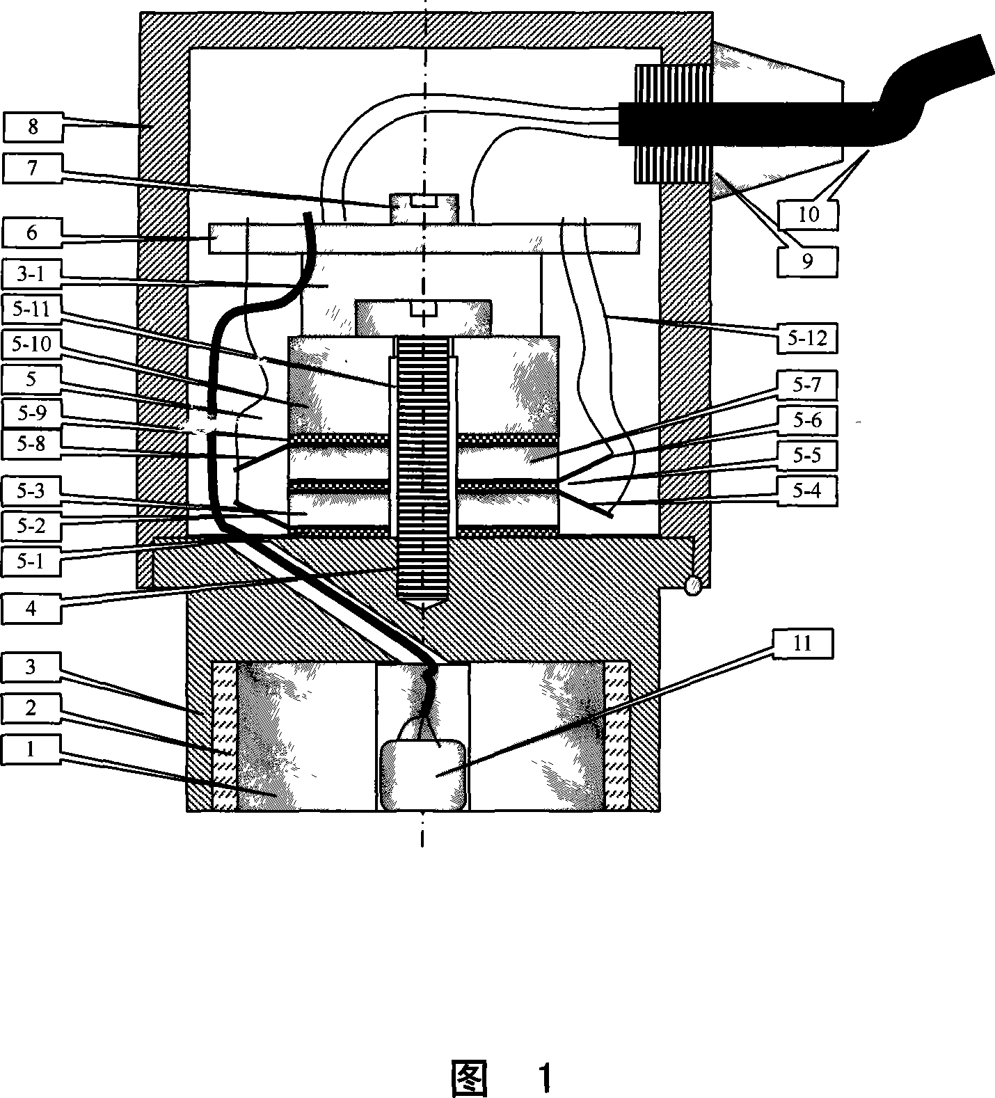
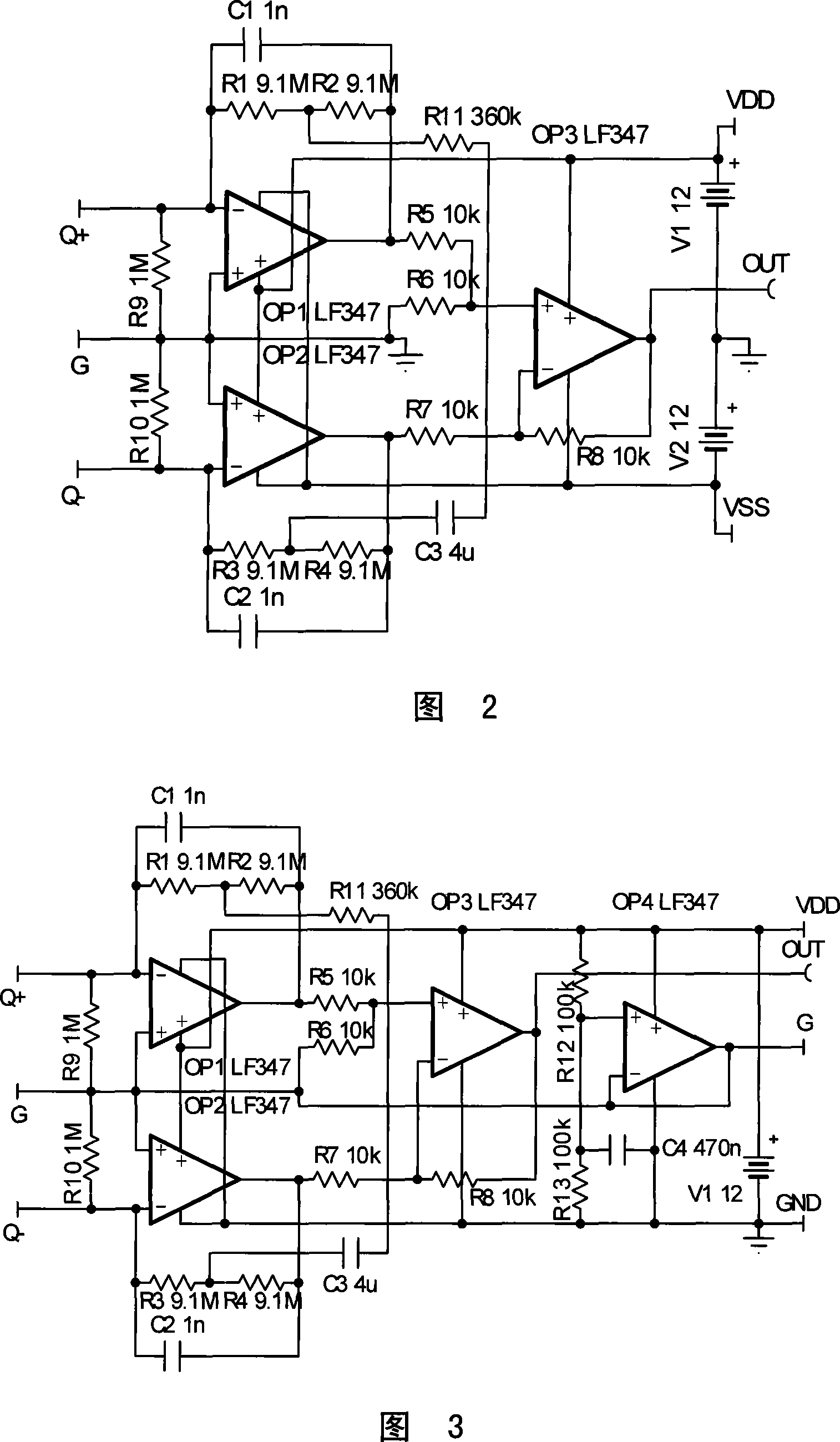
[0029] Embodiment 1 is a magnetically mounted sensor and a dual power supply differential charge amplifier (see accompanying drawing 2) for detecting vibration and shock under high temperature conditions. Due to the detection of vibration and shock under high temperature conditions, the electronic conditioner cannot be installed inside the sensor , only the charge signal generated by the piezoelectric ceramic sensitive vibration shock can be directly transferred to the corresponding signal line output of the output cable 10 through the lead wire 5-12, and the signal processing is completed by the conditioner circuit outside the sensor such as the detection instrument. In order to prevent interference, the charge signal of piezoelectric ceramics is differentially output to an external differential charge amplifier, which contains an operational amplifier OP 1 ~ OP 3 , resistor R 1 ~R 10 , capacitor C 1 ~C 3 , power terminal V DD , V SS , G and signal terminals Q+, Q-, OUT...

Embodiment 2

[0031] Embodiment 2 is a kind of magnetic mounting sensor and its single power supply differential charge amplifier (seeing accompanying drawing 3) for detecting vibration shock, it is characterized in that on the basis of embodiment 1, remove negative power supply V SS , connect the negative power supply terminal of the op amp to the ground wire GND, and increase the op amp OP 4 and resistor R 12 , R 13 and capacitor C 4 , resistor R 12 One end of the V DD , the other end is connected to the op amp OP 1 The positive input terminal is also connected to the resistor R 13 one end of the capacitor C 4 One end of the capacitor C 4 and resistor R 13 The other end of the ground is GND, and the op amp OP 4 The output terminal of the negative input terminator, and the output terminal is the level established by the charge amplifier equal to the power supply voltage V DD Half of the reference terminal G, the reference terminal is separated from the ground GND. The output sig...

Embodiment 3

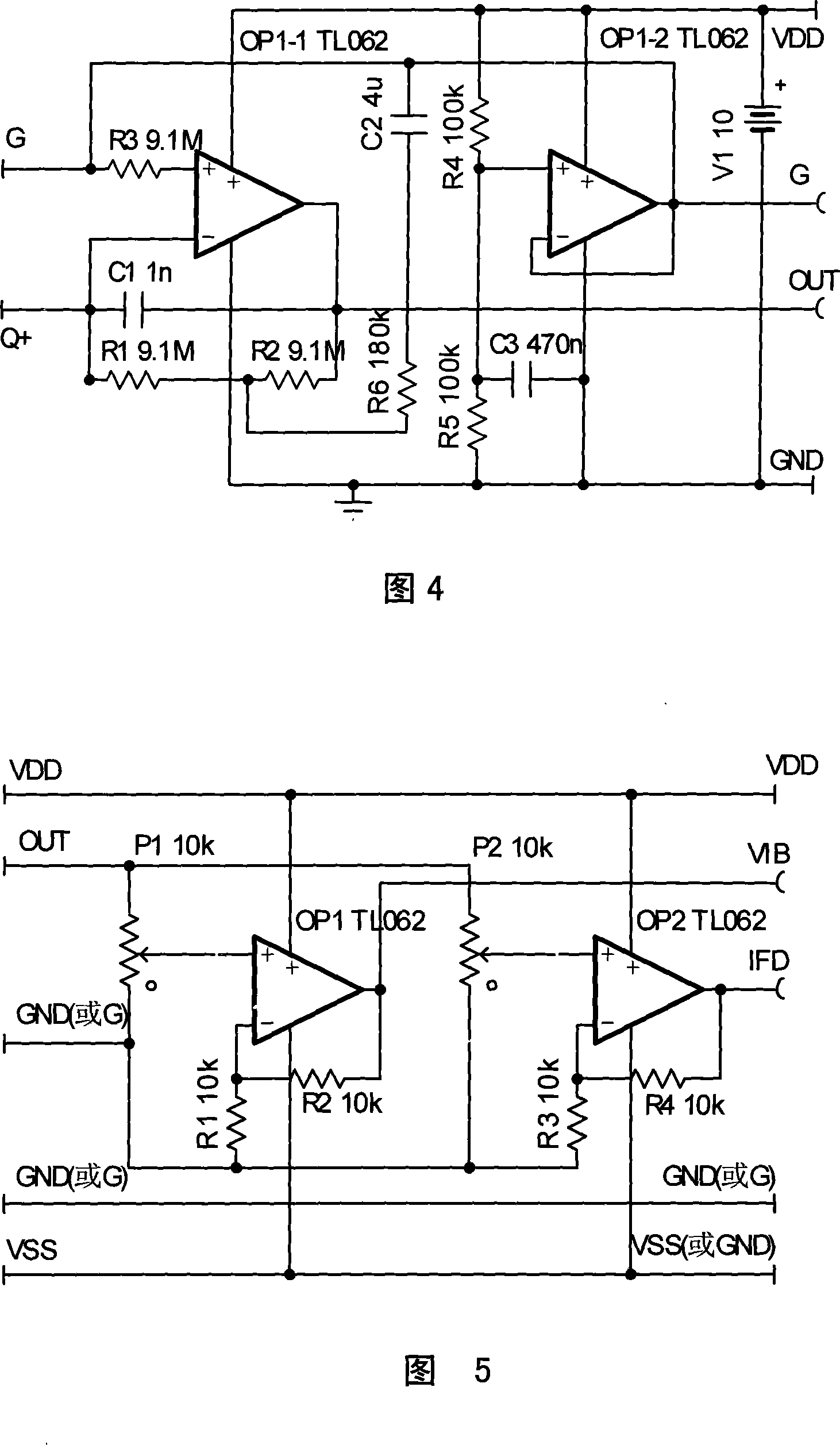
[0032] Embodiment 3 is a magnetically mounted sensor (see accompanying drawing 4) that is used to detect vibration shocks under normal temperature conditions and contains a single-ended single-supply charge amplifier installed on the conditioner 6. The output charge of the piezoelectric ceramic is connected to the sensor The built-in conditioner 6 outputs the vibration shock signal in the form of voltage after the charge / voltage conversion. Although the conditioner 6 can use the differential charge amplifier shown in Fig. 2 and 3, since the differential charge amplifier involves many types of power , leading to unreliability due to many external connecting lines, and the charge signal of piezoelectric ceramics is not easily disturbed by the charge-voltage conversion inside the sensor, so the single-ended charge amplifier as shown in Figure 4 is selected, including the operational amplifier OP 1-1 , OP 1-2 , resistor R 1 ~R 6 , Capacitor C 1 ~C 3 , input terminal Q+, output...


PUM


Abstract

A magnetic arranged vibration shook sensor comprises a shell, permanent magnetic steel, a diamagnetism spacer ring, a base, piezoelectricity component and a signal conditioner, wherein, the shell and the base are closely fitted, assembled, and, after welded, combined to form a closed installation space wherein the piezoelectricity component and the signal conditioner are arranged at the upper part, and form a installation space for permanent magnetic steel in the base; the piezoelectricity component consists of an insulation sheet, an upper conducting strip, a lower conducting strip, an upper electroceramics, a lower electroceramics, a positive conducting strip, a negative conducting strip and a quality block, and is connected to the base through screws; the signal conditioner is arranged on a supporting frame of the piezoelectricity component; the diamagnetism spacer ring, the excircle of which is coated with glue, is firstly pressed into the bottom hole of the base made of ferromagnetic material, then the permanent magnetic steel with high parallelism, finish and planeness is pressed into the center hole of the base, a thin layer of spirit glue with high intensity and high hardness is filled coordinately, the inner disk of the diamagnetism spacer ring is provided with a plurality of equally distributed small grooves which are connected with the magnetic steel and the spacer ring hard through glue; meanwhile, various electric sensing circuits are arranged according to requirements in order to form the magnetic arranged vibration shook sensor.

Description

Technical field: [0001] The invention relates to a vibration shock sensor, in particular to a magnetically mounted vibration shock sensor, which belongs to the technical category of equipment fault diagnosis and is mainly used for fault diagnosis that requires long-term reliable detection of parameters such as vibration and shock but cannot be drilled on the machine Where the sensor is installed. Background technique: [0002] In the prior art, there are vibration sensors that use magnets and existing sensors assembled by bolts and then attach the magnets to the steel material of the machine for detection, and there are also detection schemes that directly attach the existing sensors to the machine with quick-drying glue. Its disadvantage is that the scheme of connecting the existing sensor and magnet with a single bolt is prone to loose connection and failure, especially the combined contact surface between the magnet and the sensor is difficult to receive high-frequency vi...

Claims


Application Information

Patent Timeline
Patent Type & Authority Applications(China)
IPC IPC(8): G01M7/00G01M7/02G01M7/08
Inventor 唐德尧王定晓王巍松
Owner 北京唐智科技发展有限公司
Why Eureka
Try Eureka